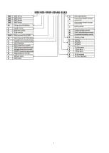
14
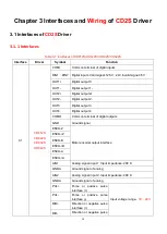
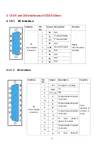
interface (-)
X2
24VS/GNDS
Logic power supply:
‖18VDC
~
30VDC 1A
‖
24VB/GNDB
Power supply for brake
―18VDC
~
30VDC 0.5A
‖ (CD622S 2A)
BR+/BR-
Brake interface
X3
CD412S
CD422S
U/V/W/PE
Motor cable interface
L/N
Main power supply
(
Single-phase AC220V
)
RB+/RB-
Braking resistor interface
X5
CD412S
CD422S
CD432S
CD622S
RS232
RS232 interface
X6
ENCODER
IN
Encoder cable interface
X7
CD432S
CD622S
R/S/T
Main power supply
(
CD432S
:
Single phase or 3-phase
AC220V
,
CD622S
:
3-phase AC380V
)
RB+/RB-
Braking resistor interface
DC+/DC-
DC bus power supply(Cannot use together with R/S/T)
Summary of Contents for CD2S Series
Page 7: ...7...
Page 8: ...8 1 3 3 Power Brake and Encoder cable of Motors...
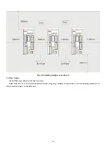
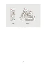
Page 12: ...12 Fig 2 3 Installation direction...
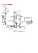
Page 15: ...15 3 1 2 Wiring Diagram Fig 3 1 Wiring diagram of CD2S driver...
Page 23: ...23 Fig 4 3 Separate regulation of bits...
Page 82: ...82...
Page 96: ...96 8 4 Debugging example 8 4 1 Oscilloscope 1 Enter oscilloscope 2 Parameters for Oscilloscope...
Page 98: ...98 In Auto Reverse mode Kvp 110...
Page 100: ...100 The oscilloscope is as following max following error is 69 inc Fig 2 Kpp 30 Vff 100...
Page 101: ...101 The oscilloscope is as following max following error is 53 inc Fig 3 Kpp 30 Vff 50...
Page 102: ...102 The oscilloscope is as following max following error is 230 inc...

