48
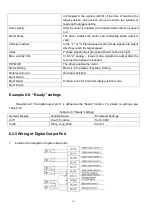
Example 6-2: Simulate digital input DIN1
Table 6-6: Simulate digital input DIN1
①
②
③
④
Input/output port selection
Set to 1 (input port
selected)
Channel selection
Set to 1 (DIN 1 selected)
Reserved
0: Invalid DIN1 simulation
1: Valid DIN1 simulation
Namely, if d3.09 is set to ―110.0‖, it indicates that no DIN1 input signals are simulated; if d3.09 is set to ―110.1‖,
it indicates that DIN1 input signals are simulated.
6.1.3 Status Display of Digital Input Signals
Table 6-7 Variables for status display of digital input signals
Numeric Display
Variable Name
Meaning
d1.11
Din_Status
Status of input ports
Din_Status (hexadecimal) is used to display the status of the actually input external signals in real time.
6.1.4 Addresses & Functions of Digital Input Signals
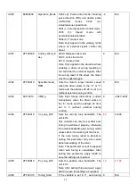
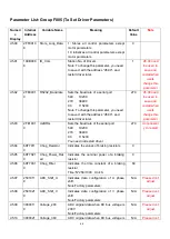
Table 6-8 Addresses & default functions of digital input signals
Numeric
Display
Variable
Name
Meaning
Default Value
d3.01
Din1_Function
000.1: Driver enable
000.2: Driver fault reset
000.4: Operation mode control
000.8: P control for velocity loop
001.0: Position positive limit
002.0: Position negative limit
004.0: Homing signal
008.0: Reverse speed demand
010.0: Internal speed control 0
020.0: Internal speed control 1
800.1: Internal speed control 2
040.0: Internal position control 0
080.0: Internal position control 1
800.2: Internal position control 2
800.4 Multi Din 0
800.8 Multi Din 1
801.0 Multi Din 2
802.0 Gain switch 0
804.0 Gain switch 1
100.0: Quick stop
200.0: Start homing
000.1 (Driver enable)
d3.02
Din2_Function
000.2 (Driver fault reset)
d3.03
Din3_Function
000.4 (Operation mode control)
d3.04
Din4_Function
000.8 (P control for velocity
loop)
d3.05
Din5_Function
001.0 (Position positive limit)
d3.06
Din6_Function
002.0 (Position negative limit)
d3.07
Din7_Function
004.0 (Homing signal)
Summary of Contents for CD2S Series
Page 7: ...7...
Page 8: ...8 1 3 3 Power Brake and Encoder cable of Motors...
Page 12: ...12 Fig 2 3 Installation direction...
Page 15: ...15 3 1 2 Wiring Diagram Fig 3 1 Wiring diagram of CD2S driver...
Page 23: ...23 Fig 4 3 Separate regulation of bits...
Page 82: ...82...
Page 96: ...96 8 4 Debugging example 8 4 1 Oscilloscope 1 Enter oscilloscope 2 Parameters for Oscilloscope...
Page 98: ...98 In Auto Reverse mode Kvp 110...
Page 100: ...100 The oscilloscope is as following max following error is 69 inc Fig 2 Kpp 30 Vff 100...
Page 101: ...101 The oscilloscope is as following max following error is 53 inc Fig 3 Kpp 30 Vff 50...
Page 102: ...102 The oscilloscope is as following max following error is 230 inc...


