99
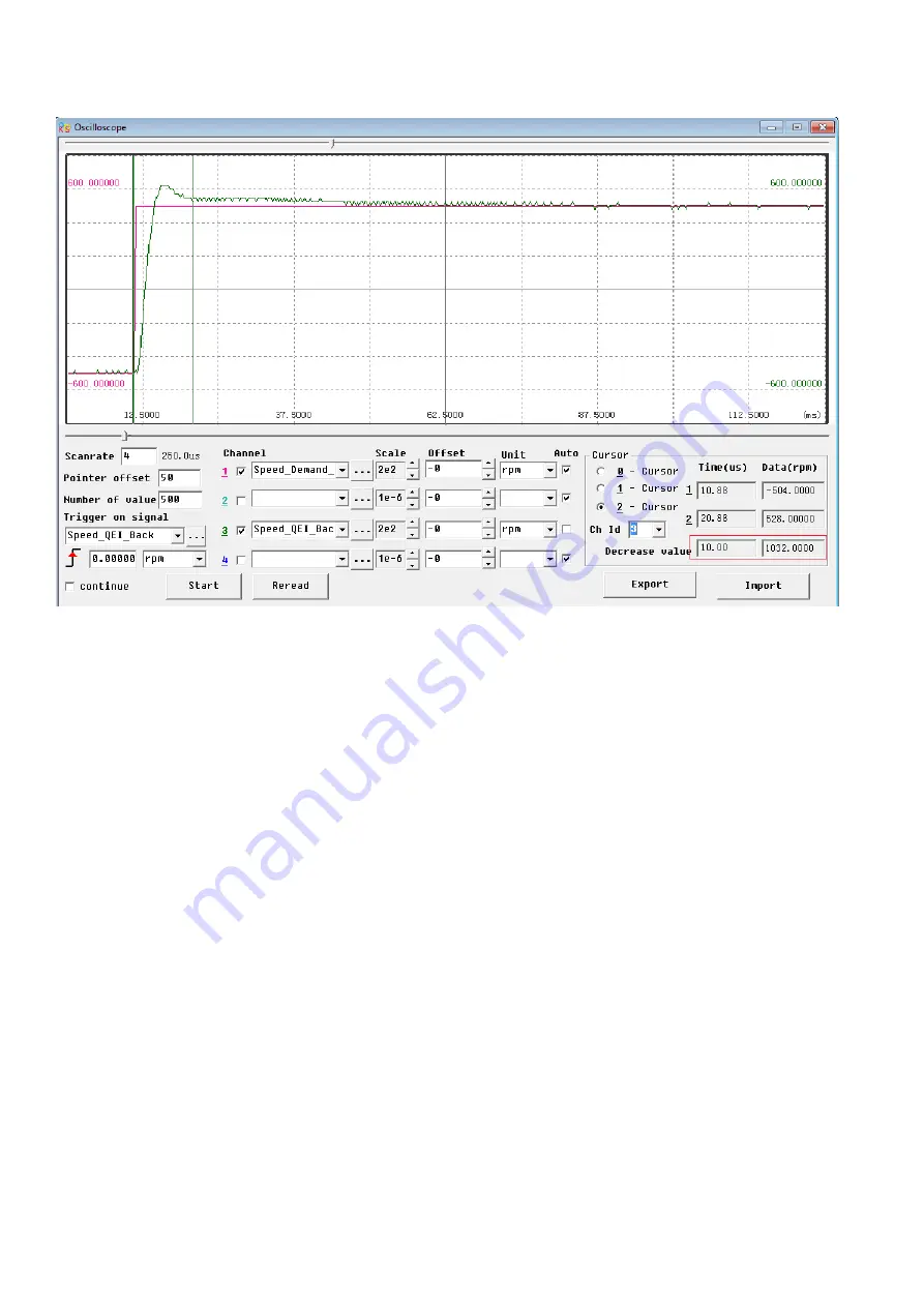
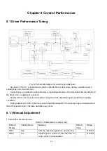
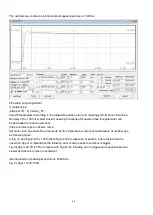
The oscilloscope is shown as follows:actual speed response is 10.00ms
2.Position Loop Adjustment
(1) Adjust Kpp.
(2)Adjust Vff
(
K_Velocity_FF
)
Adjust Vff parameter according to the allowable position error and coupling performance of machine.
Normally Vff is 100%.If system doesn’t need high response for position,then this parameter can
be decreased to reduce overshoot.
(3)Use oscilloscope to observe curve.
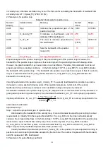
Set motor running at Auto Reverse mode by time (Operation mode 3),set parameters of oscilloscope
as following figure.
In Fig.(1) and Fig.(2),Vff is 100%,When Kpp is 30,the response of position loop is faster than the
one when Kpp is 10.Meanwhile the following error is also less,but overshoot is bigger.
Fig.(3),Kpp is 30,Vff is 50%.Compare with Fig.(2),the following error is bigger,but response becomes
slower and there is almost no overshoot.
Internal position mode,target position is 50000 inc.
Fig.(1) Kpp=10,Vff=100%
Summary of Contents for CD2S Series
Page 7: ...7...
Page 8: ...8 1 3 3 Power Brake and Encoder cable of Motors...
Page 12: ...12 Fig 2 3 Installation direction...
Page 15: ...15 3 1 2 Wiring Diagram Fig 3 1 Wiring diagram of CD2S driver...
Page 23: ...23 Fig 4 3 Separate regulation of bits...
Page 82: ...82...
Page 96: ...96 8 4 Debugging example 8 4 1 Oscilloscope 1 Enter oscilloscope 2 Parameters for Oscilloscope...
Page 98: ...98 In Auto Reverse mode Kvp 110...
Page 100: ...100 The oscilloscope is as following max following error is 69 inc Fig 2 Kpp 30 Vff 100...
Page 101: ...101 The oscilloscope is as following max following error is 53 inc Fig 3 Kpp 30 Vff 50...
Page 102: ...102 The oscilloscope is as following max following error is 230 inc...


