66
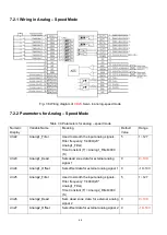
7.2.1 Wiring in Analog
– Speed Mode
Fig. 7-6 Wiring diagram of
CD2S
Servo in analog
–speed mode
7.2.2 Parameters for Analog
– Speed Mode
Table 7-9 Parameters for analog
– speed mode
Numeric
Display
Variable Name
Meaning
Default
Value
Range
d3.22
Analog1_Filter
Used to smooth the input analog signals.
Filter frequency: f=4000/(2π*
Analog1_Filter)
Time Constant (T) = Analog1_Filter/4000
(S)
5
1~127
d3.23
Analog1_Dead
Sets dead zone data for external analog
signal 1
0
0~10V
d3.24
Analog1_Offset
Sets offset data for external analog signal 1 0
-10~10V
d3.25
Analog2_Filter
Used to smooth the input analog signals.
Filter frequency: f=4000/(2π*
Analog1_Filter)
Time Constant (T) = Analog2_Filter/4000
(S)
5
1~127
d3.26
Analog2_Dead
Sets dead zone data for external analog
signal 2
0
0~10V
d3.27
Analog2_Offset
Sets offset data for external analog signal 2 0
-10~10V
Summary of Contents for CD2S Series
Page 7: ...7...
Page 8: ...8 1 3 3 Power Brake and Encoder cable of Motors...
Page 12: ...12 Fig 2 3 Installation direction...
Page 15: ...15 3 1 2 Wiring Diagram Fig 3 1 Wiring diagram of CD2S driver...
Page 23: ...23 Fig 4 3 Separate regulation of bits...
Page 82: ...82...
Page 96: ...96 8 4 Debugging example 8 4 1 Oscilloscope 1 Enter oscilloscope 2 Parameters for Oscilloscope...
Page 98: ...98 In Auto Reverse mode Kvp 110...
Page 100: ...100 The oscilloscope is as following max following error is 69 inc Fig 2 Kpp 30 Vff 100...
Page 101: ...101 The oscilloscope is as following max following error is 53 inc Fig 3 Kpp 30 Vff 50...
Page 102: ...102 The oscilloscope is as following max following error is 230 inc...


