22
2.
Press
ENTER
. The
interface for selecting addresses is displayed.
3.
Press ▲ to adjust data as
d3.35
.
4.
Press
ENTER
to display the current value
d3.35
. Press
ENTER
again to modify the value d3.35. In this case,
the 1
st
number at the right side is flickering. Short press
MODE
for three times to move to the first position on
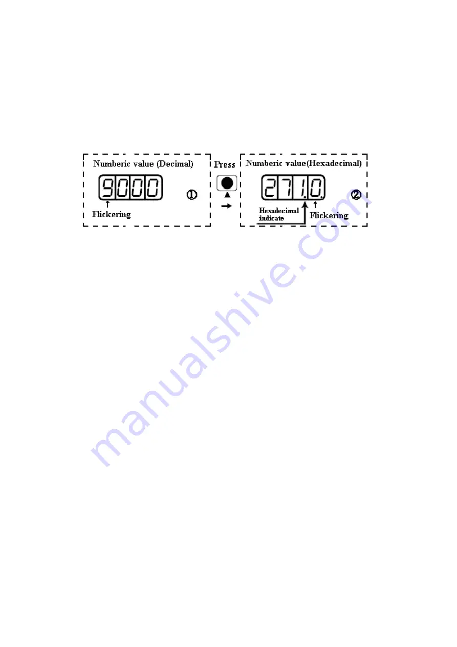
the left. Then press ▲. The value is increased to 9000. In this case, the current data is decimal.
5.
Press ▲ again. The content of numeric display changes to ―271.0‖, and the 3
rd
decimal point (from left to
right) flickers. In this case, the data is hexadecimal. Press
ENTER
to confirm the current value. The 1
st
decimal point on the right flickers. In this case, the denominator of the electronic gear ratio is modified to
10000.
Fig. 4-2 Number system conversion
Example 4-2: Set the speed to 1000 RPM/-1000 RPM with separate regulation of
bits
1.
Press
MODE
. The main menu is displayed. Choose
F000
.
2.
Press
ENTER
. The interface for selecting addresses is displayed.
3.
Press ▲ to adjust data as
d0.02
.
4.
Press
ENTER
to display the current value d0.02. Press
ENTER
again to modify the value d0.02. In this case,
the 1
st
number at the right side is flickering.
5.
Short press
MODE
for three times to move to the 1
st
position on the left. Press ▲ to modify the value to 1.
Press
ENTER
to confirm the current value. The 1
st
decimal point on the right flickers. In this case, the speed
is 1000 RPM.
6.
Press ▼ to modify the value to -1. In this case, the 1
st
decimal point on the left flickers, indicating that the
current data is negative. Press
ENTER
to confirm the current value. The 1
st
decimal point on the right flickers.
In this case, the speed is -10000 RPM.
Summary of Contents for CD2S Series
Page 7: ...7...
Page 8: ...8 1 3 3 Power Brake and Encoder cable of Motors...
Page 12: ...12 Fig 2 3 Installation direction...
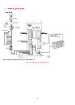
Page 15: ...15 3 1 2 Wiring Diagram Fig 3 1 Wiring diagram of CD2S driver...
Page 23: ...23 Fig 4 3 Separate regulation of bits...
Page 82: ...82...
Page 96: ...96 8 4 Debugging example 8 4 1 Oscilloscope 1 Enter oscilloscope 2 Parameters for Oscilloscope...
Page 98: ...98 In Auto Reverse mode Kvp 110...
Page 100: ...100 The oscilloscope is as following max following error is 69 inc Fig 2 Kpp 30 Vff 100...
Page 101: ...101 The oscilloscope is as following max following error is 53 inc Fig 3 Kpp 30 Vff 50...
Page 102: ...102 The oscilloscope is as following max following error is 230 inc...


