28
5.2.3 Operating Steps
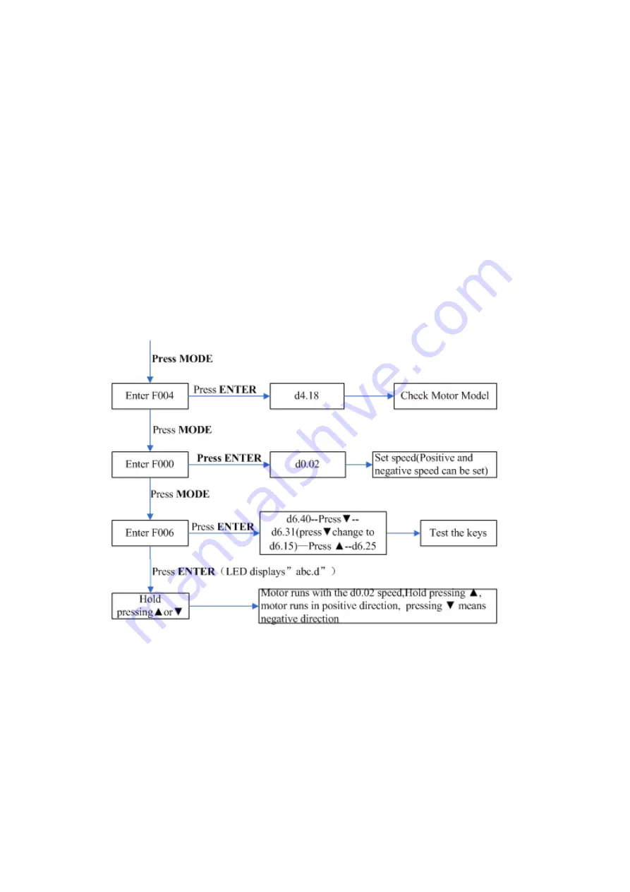
1. Press
MODE
to enter Group F004. Select the object address ―d4.18‖, and check the motor type.
2. Press
MODE
to enter Group F000. Select the object address ―d0.02‖, and set the target speed to
―SpeedDemand_RPM".
3. Press
MODE
to enter Group F006. Arrange a test for keys, with the default value of d6.40. Firstly, press
▼ to adjust the data to d6.31. Then, press ▼, the data automatically changes to ―d6.15‖. Finally, press ▲
to adjust the data to d6.25.
4. Press
ENTER
to activate trial operation. In this case, the numeric display is ―adc.d‖, and the motor shaft
releases. When long pressing ▲ or ▼, the motor automatically locks, and runs according to
―+SpeedDemand_RPM‖ or ―-SpeedDemand_RPM‖ separately. During the trial operation, the numeric
displays the motor speed in real time.
5.2.4 Diagram of Trial Operation
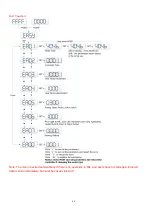
Fig.5-4 Flow chart for trial operation
5.3 EASY USE
Easy use is used to help users rapidly set control loop parameters, so as to avoid complex steps of adjusting
servo.
After adjusting, driver's performance will be fine in most of applications. And this also open another isolated
area, which is convenient for users
to set significant parameters.
Summary of Contents for CD2S Series
Page 7: ...7...
Page 8: ...8 1 3 3 Power Brake and Encoder cable of Motors...
Page 12: ...12 Fig 2 3 Installation direction...
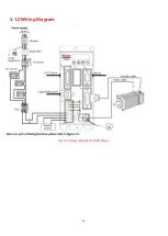
Page 15: ...15 3 1 2 Wiring Diagram Fig 3 1 Wiring diagram of CD2S driver...
Page 23: ...23 Fig 4 3 Separate regulation of bits...
Page 82: ...82...
Page 96: ...96 8 4 Debugging example 8 4 1 Oscilloscope 1 Enter oscilloscope 2 Parameters for Oscilloscope...
Page 98: ...98 In Auto Reverse mode Kvp 110...
Page 100: ...100 The oscilloscope is as following max following error is 69 inc Fig 2 Kpp 30 Vff 100...
Page 101: ...101 The oscilloscope is as following max following error is 53 inc Fig 3 Kpp 30 Vff 50...
Page 102: ...102 The oscilloscope is as following max following error is 230 inc...


