26
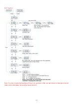
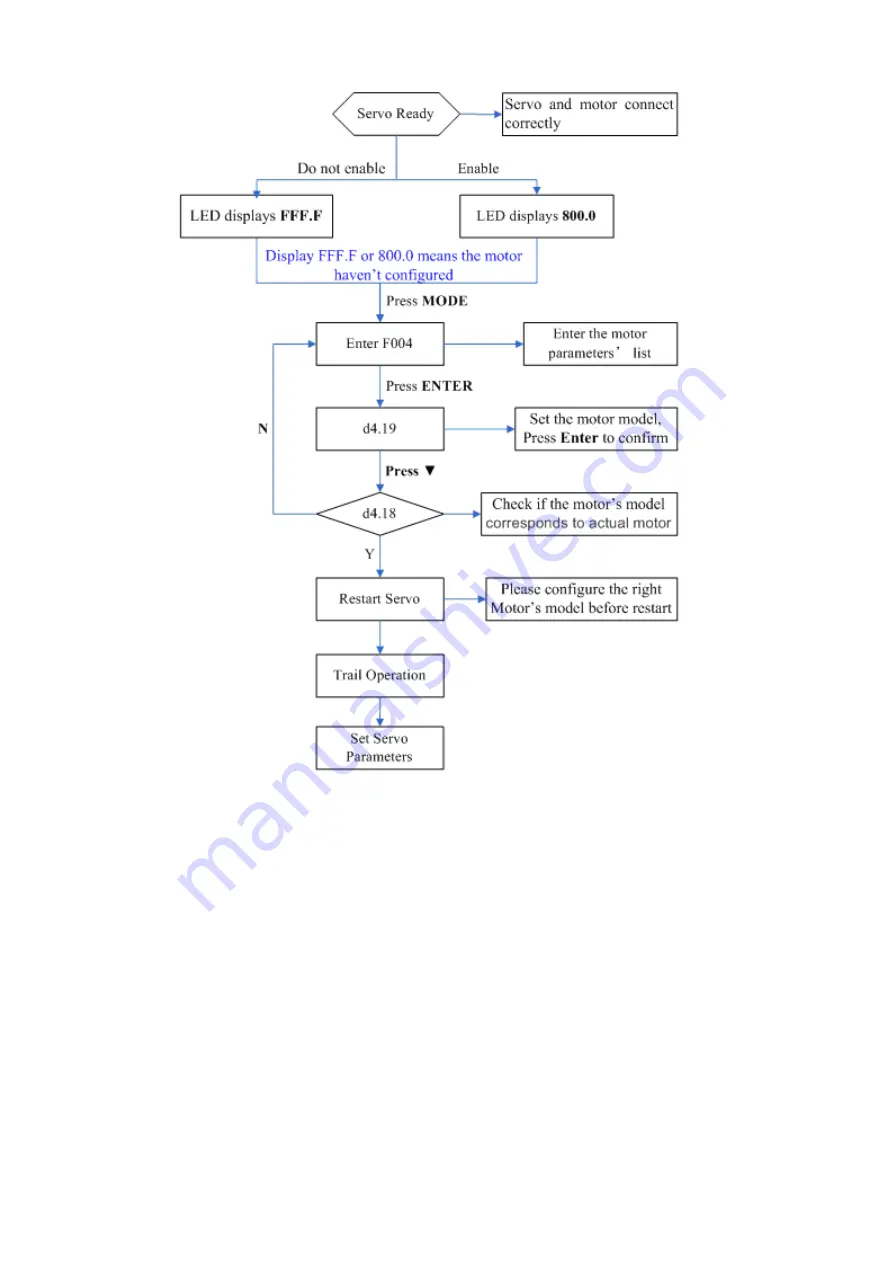
Fig.5-2 Flow chart for configuring motor by key
Please configure the right motor’s model before restart.
If customers want to reset the motor model,
they should set D4.19 to 303.0 (Press ENTER to confirm) and then d4.00 to 1(Save motor parameters), after
restart the servo they can reset motor model and servo parameters according to the above chart
(2) Configure Motor (
CD-PC Software Operation
)
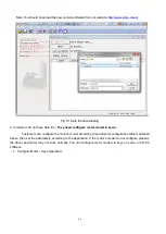
Connect the servo to PC, open the CD-PC, then Menu
—Driver—Control Panel—F004, in the F004, in
the F004, set the 19th operation:
Motor Num
(Please refer to the servo and motor configuration table), after
that press Enter to confirm, then restart servo.
Please configure the right Motor’s model before restart.
If the customers want to reset the motor
model, they should set D4.19 (Motor Num in F004) to 00(Press ENTER to confirm), then enter the
Initialize/Save
page, click the
Save motor parameters.
After restart the servo, they can reset the motor
model and set servo parameters.
Summary of Contents for CD2S Series
Page 7: ...7...
Page 8: ...8 1 3 3 Power Brake and Encoder cable of Motors...
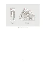
Page 12: ...12 Fig 2 3 Installation direction...
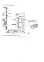
Page 15: ...15 3 1 2 Wiring Diagram Fig 3 1 Wiring diagram of CD2S driver...
Page 23: ...23 Fig 4 3 Separate regulation of bits...
Page 82: ...82...
Page 96: ...96 8 4 Debugging example 8 4 1 Oscilloscope 1 Enter oscilloscope 2 Parameters for Oscilloscope...
Page 98: ...98 In Auto Reverse mode Kvp 110...
Page 100: ...100 The oscilloscope is as following max following error is 69 inc Fig 2 Kpp 30 Vff 100...
Page 101: ...101 The oscilloscope is as following max following error is 53 inc Fig 3 Kpp 30 Vff 50...
Page 102: ...102 The oscilloscope is as following max following error is 230 inc...

