31
Users must save control and motor parameters and reboot the controller
after changing the motor type in EA01.
After saving the parameters, the servo will set the control loop parameters
according to the load type and application.
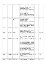
Table 2 Stiffness and control loop settings
Stiffness
Kpp/[0.01Hz]
Kvp/[0.1Hz]
Output filter
[Hz]
Stiffness
Kpp/[0.01Hz]
Kvp/[0.1Hz]
Output filter
[Hz]
0
70
25
18
16
1945
700
464
1
98
35
24
17
2223
800
568
2
139
50
35
18
2500
900
568
3
195
70
49
19
2778
1000
733
4
264
95
66
20
3334
1200
733
5
334
120
83
21
3889
1400
1032
6
389
140
100
22
4723
1700
1032
7
473
170
118
23
5556
2000
1765
8
556
200
146
24
6389
2300
1765
9
639
230
164
25
7500
2700
1765
10
750
270
189
26
8612
3100
1765
11
889
320
222
27
9445
3400
∞
12
1056
380
268
28
10278
3700
∞
13
1250
450
340
29
11112
4000
∞
14
1500
540
360
30
12500
4500
∞
15
1667
600
392
31
13889
5000
∞
Note: When setting for the stiffness or inertia ratio results in a Kvp value of greater than 4000, it isn't useful to
increase stiffness any more.
Summary of Contents for CD2S Series
Page 7: ...7...
Page 8: ...8 1 3 3 Power Brake and Encoder cable of Motors...
Page 12: ...12 Fig 2 3 Installation direction...
Page 15: ...15 3 1 2 Wiring Diagram Fig 3 1 Wiring diagram of CD2S driver...
Page 23: ...23 Fig 4 3 Separate regulation of bits...
Page 82: ...82...
Page 96: ...96 8 4 Debugging example 8 4 1 Oscilloscope 1 Enter oscilloscope 2 Parameters for Oscilloscope...
Page 98: ...98 In Auto Reverse mode Kvp 110...
Page 100: ...100 The oscilloscope is as following max following error is 69 inc Fig 2 Kpp 30 Vff 100...
Page 101: ...101 The oscilloscope is as following max following error is 53 inc Fig 3 Kpp 30 Vff 50...
Page 102: ...102 The oscilloscope is as following max following error is 230 inc...


