9
Chapter 2 Precautions and Installation
Requirements
A Kinco
CD2S
series servo driver is installed on a base. If a driver is not installed properly, some faults may
occur. To avoid this, install the driver by abiding by the following precautions.
2.1 Precautions
1. Tightly fasten the screws that fix the motor;
2. Make sure to tightly fasten all fixed points when fixing the driver;
3. Do not tighten the cables between the driver and the motor/encoder;
4. Use a coupling shaft or expansion sleeve to ensure that both the motor shaft and equipment shaft are
properly centered;
5. Do not mix conductive materials (such as screws and metal filings) or combustible materials (such as oil) into
the servo driver;
6. Avoid the servo driver and servo motor from dropping or striking because they are precision equipment;
7. For safety, do not use any damaged servo driver or any driver with damaged parts.
2.2 Environmental Conditions
Table 2-1 Environmental conditions
Environment
Condition
Temperature
Operating temperature: 0
C - 40
C (ice free)
Storage temperature: - 10
C - 70
C (ice free)
Humidity
Operating humidity: below 90% PH (non-condensing)
Storage humidity: below 90% PH (non-condensing)
Air
Indoor (No direct sunlight), no corrosive gas or combustible gas
No oil vapor or dust
Height
Below 1000 m above the sea level
Vibration
5.9 m/s2
2.3 Mounting Direction & Spacing
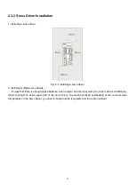
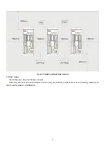
2.3.1 Precautions
1. To prevent possible faults, install a servo driver in a proper direction;
2. To prevent possible faults, ensure that the space between a servo driver and the inner wall of the control
cabinet as well as that between the servo driver and the neighboring driver are the same as specified space..
Summary of Contents for CD2S Series
Page 7: ...7...
Page 8: ...8 1 3 3 Power Brake and Encoder cable of Motors...
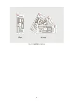
Page 12: ...12 Fig 2 3 Installation direction...
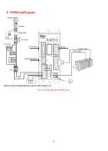
Page 15: ...15 3 1 2 Wiring Diagram Fig 3 1 Wiring diagram of CD2S driver...
Page 23: ...23 Fig 4 3 Separate regulation of bits...
Page 82: ...82...
Page 96: ...96 8 4 Debugging example 8 4 1 Oscilloscope 1 Enter oscilloscope 2 Parameters for Oscilloscope...
Page 98: ...98 In Auto Reverse mode Kvp 110...
Page 100: ...100 The oscilloscope is as following max following error is 69 inc Fig 2 Kpp 30 Vff 100...
Page 101: ...101 The oscilloscope is as following max following error is 53 inc Fig 3 Kpp 30 Vff 50...
Page 102: ...102 The oscilloscope is as following max following error is 230 inc...

