44
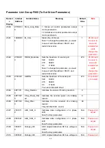
Parameter List: Group F005 (To Set Driver Parameters)
Numeri
c
Display
Internal
Address
Variable Name
Meaning
Default
Value
Note
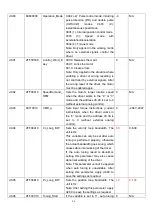
d5.00
2FF0010
8
Store_Loop_Data
1: Stores all control parameters except
motor parameters
10: Initializes all control parameters except
motor parameters
0
d5.01
100B000
8
ID_Com
Station No. of Drivers
Note: To change this parameter, you need
to save it with the address ―d5.00‖, and
restart driver later.
1
d5.00 need
be used to
save and
restart when
users
change this
parameter
d5.02
2FE0001
0
RS232_Bandrate
Sets the baud rate of a serial port
540 19200
270 38400
90 115200
Note: To change this parameter, you need
to save it with the address ―d5.00‖, and
restart driver later.
270
d5.00 need
be used to
save and
restart when
users
change this
parameter
d5.03
2FE1001
0
U2BRG
Sets the baud rate of the serial port
540 19200
270 38400
90 115200
You need not restart driver.
270
Unnecessar
y to restart
d5.04
60F7011
0
Chop_Resistor
Indicates the values of braking resistors
0
d5.05
60F7021
0
Chop_Power_Rat
ed
Indicates the nominal power of a braking
resistor
0
d5.06
60F7031
0
Chop_Filter
Indicates the time constant of a braking
resistor
Time: N*256/1000 Unit: S
60
d5.07
2501011
0
ADC_Shift_U
Indicates data configuration of U phase
shift
Note:Factory parameters
N/A
Please don
’t
adjust
d5.08
2501021
0
ADC_Shift_V
Indicates data configuration of V phase
shift
Note:Factory parameters
N/A
Please don
’t
adjust
d5.09
3000011
0
Voltage_200
ADC original data when DC bus voltage is
200 V
Note:Factory parameters
N/A
Please don
’t
adjust
d5.10
3000021
Voltage_360
ADC original data when DC bus voltage is
N/A
Please don
’t
Summary of Contents for CD2S Series
Page 7: ...7...
Page 8: ...8 1 3 3 Power Brake and Encoder cable of Motors...
Page 12: ...12 Fig 2 3 Installation direction...
Page 15: ...15 3 1 2 Wiring Diagram Fig 3 1 Wiring diagram of CD2S driver...
Page 23: ...23 Fig 4 3 Separate regulation of bits...
Page 82: ...82...
Page 96: ...96 8 4 Debugging example 8 4 1 Oscilloscope 1 Enter oscilloscope 2 Parameters for Oscilloscope...
Page 98: ...98 In Auto Reverse mode Kvp 110...
Page 100: ...100 The oscilloscope is as following max following error is 69 inc Fig 2 Kpp 30 Vff 100...
Page 101: ...101 The oscilloscope is as following max following error is 53 inc Fig 3 Kpp 30 Vff 50...
Page 102: ...102 The oscilloscope is as following max following error is 230 inc...


