35
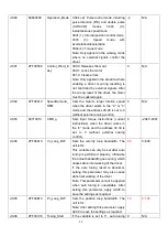
d0.00
60600008
Operation_Mode 0.004 (-4): Pulse control mode, including
pulse direction (P/D) and double pulse
(CW/CCW)
modes.
0.003
(-3):
instantaneous speed mode
0001 (1): Internal position control mode
0003
(3):
Speed
mode
with
acceleration/deceleration
0004 (4): Torque mode
Note: Only applied in the working mode
where no external signals control the
driver.
-4
N/A
d0.01
2FF00508
Control_Word_E
asy
000.0: Releases the motor
000.1: Locks the motor
001.0: Clears errors
Note: Only applied in the situation where
enabling a driver or wrong resetting is
not controlled by external signals. After
the wrong reset of the driver, the motor
must be enabled again.
0
N/A
d0.02
2FF00910
SpeedDemand_
RPM
Sets the motor’s target rotation speed
when the driver works in the ―-3‖ or ―3‖
mode and the address d3.28 is set to 0
(without external analog control).
0
N/A
d0.03
60710010
CMD_q
Sets input torque instructions (current
instructions) when the driver works in
the ―4‖ mode and the address d3.30 is
set to 0 (without external analog
control).
0
-2047~2047
d0.04
2FF00A10
Vc_Loop_BW
Sets the velocity loop bandwidth. The
unit is Hz.
This variable can only be set after auto
tuning is performed properly; otherwise
the actual bandwidth goes wrong, which
causes abnormal working of the driver.
If the auto tuning result is abnormal,
setting this parameter may also cause
abnormal working of the driver.
Note: This parameter cannot be applied
when auto tuning is unavailable. After
setting this parameter, apply d2.00 to
save the settings as required.
60
0~600
d0.05
2FF00B10
Pc_Loop_BW
Sets the position loop bandwidth. The
unit is Hz.
Note: After setting this parameter, apply
d2.00 to save the settings as required.
10
0~100
d0.06
2FF00C10
Tuning_Start
If the variable is set to 11, auto tuning 0
N/A
Summary of Contents for CD2S Series
Page 7: ...7...
Page 8: ...8 1 3 3 Power Brake and Encoder cable of Motors...
Page 12: ...12 Fig 2 3 Installation direction...
Page 15: ...15 3 1 2 Wiring Diagram Fig 3 1 Wiring diagram of CD2S driver...
Page 23: ...23 Fig 4 3 Separate regulation of bits...
Page 82: ...82...
Page 96: ...96 8 4 Debugging example 8 4 1 Oscilloscope 1 Enter oscilloscope 2 Parameters for Oscilloscope...
Page 98: ...98 In Auto Reverse mode Kvp 110...
Page 100: ...100 The oscilloscope is as following max following error is 69 inc Fig 2 Kpp 30 Vff 100...
Page 101: ...101 The oscilloscope is as following max following error is 53 inc Fig 3 Kpp 30 Vff 50...
Page 102: ...102 The oscilloscope is as following max following error is 230 inc...


