Goodrive200
inverters Basic operation instruction
188
according to the changing trend when it fluctuates. Because the derivation may enlarge the
interference to the system, especially the frequent-changing interference, please use it carefully.
When P00.06, P00. 07=7 or P04.27=6, the running mode of the inverter is procedure PID control.
7.15.1 General steps of PID parameters setting:
a
Ensure the gain P
When ensure the gain P, firstly cancel the PID integration and derivation (set Ti=0 and Td=0, see
the PID parameter setting for detailed information) to make proportional adjustment is the only
method to PID. Set the input as 60%~70% of the permitted Max. Value and increase gain P from 0
until the system vibration occurs, vice versa, and record the PID value and set it to 60%~70% of
the current value. Then the gain P commission is finished.
b Ensure the integration time
After ensuring the gain P, set an original value of a bigger integration time and decrease it until the
system vibration occurs, vice versa, until the system vibration disappear. Record the Ti and set the
integration time to 150%~180% of the current value. Then integration time commission is finished.
c Ensure the derivation time
Generally, it is not necessary to set Td which is 0.
If it needs to be set, set it to 30% of the value without vibration via the same method with P and Ti.
d
Commission the system with and without load and then adjust the PID parameter until it is
available.
7.15.2 PID inching
After setting the PID control parameters, inching is possible by following means:
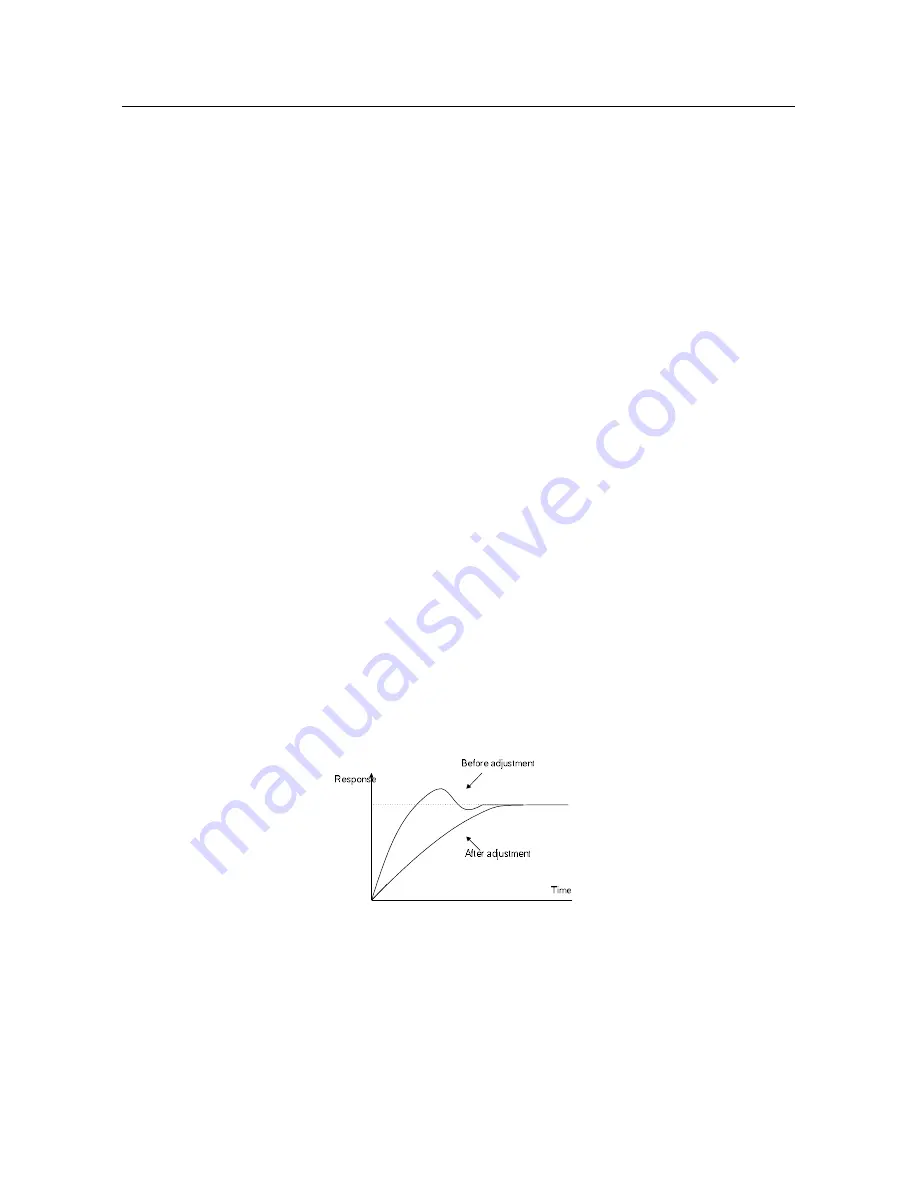
Control the overshoot
Shorten the derivation time and prolong the integration time when overshoot occurs.
Achieve the stable state as soon as possible
Shorten the integration time (Ti) and prolong the derivation time (Td) even the overshoot occurs,
but the control should be stable as soon as possible.
Summary of Contents for GD200-037G/045P-4
Page 1: ...Goodrive 200 Inverter ...
Page 44: ...Goodrive200 inverters Keypad operation procedure 43 Fig 5 5 Sketch map of state watching ...
Page 158: ...Goodrive200 inverters Basic operation instruction 157 ...
Page 208: ...Goodrive200 inverters Fault tracking 207 8 6 2 Motor vibration 8 6 3 Overvoltage ...
Page 209: ...Goodrive200 inverters Fault tracking 208 8 6 4 Undervoltage fault 8 6 5 Inverter overheating ...
Page 210: ...Goodrive200 inverters Fault tracking 209 8 6 6 Abnormal motor heat ...
Page 211: ...Goodrive200 inverters Fault tracking 210 8 6 7 Stall during the acceleration of the motor ...
Page 266: ...1 1 0 0 1 0 0 7 7 9 6 6 0 0 1 0 0 0 9 5 201701 V2 2 ...


