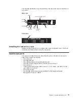
Notes:
1. All hot-swap drives being used in the server should have the same data transfer
rate. Mixing hard disk drives with different data transfer rates will cause all
drives to operate at the lower speed.
2. The SCSI ID assigned to each bay is printed on the bezel.
Attention:
To maintain proper system cooling, do not operate the server for more
than 10 minutes without either a drive or a filler panel installed in each bay.
1. Review the information in “Safety information” on page 121, and “Before you
begin” on page 41.
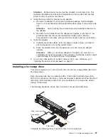
2. Remove the filler panel from one of the empty hot-swap bays by inserting your
finger into the depression at the left side of the filler panel and pulling it away
from the server.
3. Install the hard disk drive in the hot-swap bay:
a. Ensure that the tray handle is open (that is, perpendicular to the drive).
b. Align the drive assembly with the guide rails in the bay.
c. Gently push the drive assembly into the bay until the drive stops.
d. Push the tray handle to the closed (locked) position.
e. Check the hard disk drive status LED to verify that the hard disk drive is
operating properly.
If the amber hard disk drive status LED for a drive is lit continuously, that
individual drive is faulty and needs to be replaced. If the green hard disk
drive activity LED is flashing, the drive is being accessed.
Note:
If you have a RAID configuration on your server using the integrated
SCSI controller with RAID capabilities, or if your server has a RAID
adapter installed, you might need to reconfigure your disk arrays after
installing hard disk drives. See the RAID documentation on the IBM
xSeries Documentation
CD for information about RAID adapters.
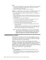
Installing memory modules
Adding memory to your server is an easy way to make programs run faster. You
can increase the amount of memory in your server by installing memory-module
options. When you install memory, you must install a pair of matched double data
rate (DDR) dual inline memory modules (DIMMs).
Attention:
Install only 2.5 V, 184-pin, double-data-rate (DDR), registered
synchronous dynamic random-access memory (SDRAM) with error correcting code
(ECC) DIMMs. These DIMMs must be compatible with the latest PC2100 (CL2.5)
specification, and downward compatible with PC1600 (CL2) SDRAM Registered
DIMM specification, which is available from http://www.jedec.org/ on the World Wide
Web. For a list of supported options for your server, go to
http://www.ibm.com/us/compat/ on the World Wide Web.
Notes:
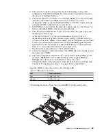
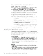
1. The system board contains four DIMM connectors and supports two-way
memory interleaving.
2. The DIMM options available for your server are 256 MB, 512 MB, and 1 GB.
Your server supports a minimum of 512 MB and a maximum of 4 GB of
system memory.
58
xSeries 345 Type 8670: Hardware Maintenance Manual and Troubleshooting Guide
Summary of Contents for eServer xSeries 345 Type 8670
Page 1: ...xSeries 345 Type 8670 Hardware Maintenance Manual and Troubleshooting Guide ERserver...
Page 2: ......
Page 3: ...xSeries 345 Type 8670 Hardware Maintenance Manual and Troubleshooting Guide ERserver...
Page 6: ...iv xSeries 345 Type 8670 Hardware Maintenance Manual and Troubleshooting Guide...
Page 10: ...viii xSeries 345 Type 8670 Hardware Maintenance Manual and Troubleshooting Guide...
Page 18: ...8 xSeries 345 Type 8670 Hardware Maintenance Manual and Troubleshooting Guide...
Page 88: ...78 xSeries 345 Type 8670 Hardware Maintenance Manual and Troubleshooting Guide...
Page 124: ...114 xSeries 345 Type 8670 Hardware Maintenance Manual and Troubleshooting Guide...
Page 130: ...120 xSeries 345 Type 8670 Hardware Maintenance Manual and Troubleshooting Guide...
Page 141: ...Chapter 8 Related service information 131...
Page 142: ...132 xSeries 345 Type 8670 Hardware Maintenance Manual and Troubleshooting Guide...
Page 143: ...Chapter 8 Related service information 133...
Page 144: ...134 xSeries 345 Type 8670 Hardware Maintenance Manual and Troubleshooting Guide...
Page 145: ...Chapter 8 Related service information 135...
Page 146: ...136 xSeries 345 Type 8670 Hardware Maintenance Manual and Troubleshooting Guide...
Page 147: ...Chapter 8 Related service information 137...
Page 157: ...Chapter 8 Related service information 147...
Page 158: ...148 xSeries 345 Type 8670 Hardware Maintenance Manual and Troubleshooting Guide...
Page 159: ...Chapter 8 Related service information 149...
Page 160: ...150 xSeries 345 Type 8670 Hardware Maintenance Manual and Troubleshooting Guide...
Page 161: ...Chapter 8 Related service information 151...
Page 162: ...152 xSeries 345 Type 8670 Hardware Maintenance Manual and Troubleshooting Guide...
Page 166: ...156 xSeries 345 Type 8670 Hardware Maintenance Manual and Troubleshooting Guide...
Page 174: ...164 xSeries 345 Type 8670 Hardware Maintenance Manual and Troubleshooting Guide...
Page 175: ......
Page 176: ...Part Number 48P9718 1P P N 48P9718...

