Bus fault messages
Note:
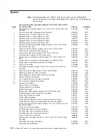
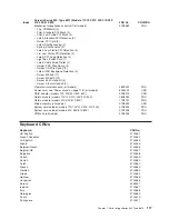
See “System” on page 116 to determine which components should be replaced by a field service technician.
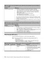
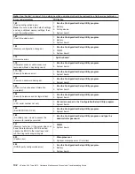
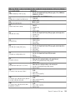
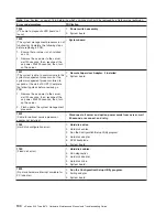
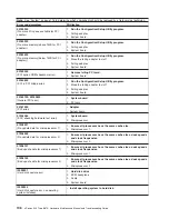
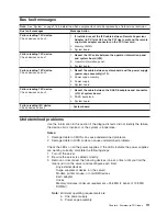
Bus fault messages
Message Action
Failure reading 12C device.
Check devices on bus 0.
1.
If installed, reseat the I2C cable between Remote Supervisor
Adapter (in PCI slot 5/J5 on the PCI riser card) and the remote
supervisor adapter connector on the PCI riser card.
2. Memory DIMMs.
3. System board.
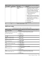
Failure reading 12C device.
Check devices on bus 1.
1.
Reseat the I2C cable between the operator information panel
and system board (J22).
2. Operator information panel.
3. System board.
Failure reading 12C device.
Check devices on bus 2.
1.
Reseat the cable between system board and the power supply
(power cage assembly) (J10).
2. Power cage assembly.
3. Power supply.
4. System board.
Failure reading 12C device.
Check devices on bus 3.
1.
Reseat the cable between the DASD backplane and connector
(J10) of system board.
2. DASD backplane.
3. System board.
Failure reading I2C device.
Check device on bus 4.
v
System board
Undetermined problems
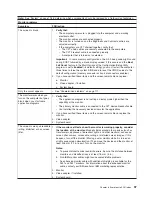
Use the information in this section if the diagnostic tests did not identify the failure,
the devices list is incorrect, or the system is inoperative.
Notes:
1. Damaged data in CMOS can cause undetermined problems.
2. Damaged data in BIOS code can cause undetermined problems.
Check the LEDs on all the power supplies. If the LEDs indicate the power supplies
are working correctly, complete the following steps:
1. Turn off the server.
2. Be sure the server is cabled correctly.
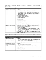
3. Remove or disconnect the following devices (one at a time) until you find the
failure (turn on the server and reconfigure each time):
Any external devices
Surge suppressor device (on the server)
Modem, printer, mouse, or non-IBM devices
Each adapter
Drives
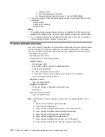
Memory modules (minimum requirement = 256 MB (2 banks of 128 MB
DIMMs))
Note:
Minimum operating requirements are:
a. One power supply
b. Power cage assembly.
Chapter 6. Symptom-to-FRU index
111
Summary of Contents for eServer xSeries 345 Type 8670
Page 1: ...xSeries 345 Type 8670 Hardware Maintenance Manual and Troubleshooting Guide ERserver...
Page 2: ......
Page 3: ...xSeries 345 Type 8670 Hardware Maintenance Manual and Troubleshooting Guide ERserver...
Page 6: ...iv xSeries 345 Type 8670 Hardware Maintenance Manual and Troubleshooting Guide...
Page 10: ...viii xSeries 345 Type 8670 Hardware Maintenance Manual and Troubleshooting Guide...
Page 18: ...8 xSeries 345 Type 8670 Hardware Maintenance Manual and Troubleshooting Guide...
Page 88: ...78 xSeries 345 Type 8670 Hardware Maintenance Manual and Troubleshooting Guide...
Page 124: ...114 xSeries 345 Type 8670 Hardware Maintenance Manual and Troubleshooting Guide...
Page 130: ...120 xSeries 345 Type 8670 Hardware Maintenance Manual and Troubleshooting Guide...
Page 141: ...Chapter 8 Related service information 131...
Page 142: ...132 xSeries 345 Type 8670 Hardware Maintenance Manual and Troubleshooting Guide...
Page 143: ...Chapter 8 Related service information 133...
Page 144: ...134 xSeries 345 Type 8670 Hardware Maintenance Manual and Troubleshooting Guide...
Page 145: ...Chapter 8 Related service information 135...
Page 146: ...136 xSeries 345 Type 8670 Hardware Maintenance Manual and Troubleshooting Guide...
Page 147: ...Chapter 8 Related service information 137...
Page 157: ...Chapter 8 Related service information 147...
Page 158: ...148 xSeries 345 Type 8670 Hardware Maintenance Manual and Troubleshooting Guide...
Page 159: ...Chapter 8 Related service information 149...
Page 160: ...150 xSeries 345 Type 8670 Hardware Maintenance Manual and Troubleshooting Guide...
Page 161: ...Chapter 8 Related service information 151...
Page 162: ...152 xSeries 345 Type 8670 Hardware Maintenance Manual and Troubleshooting Guide...
Page 166: ...156 xSeries 345 Type 8670 Hardware Maintenance Manual and Troubleshooting Guide...
Page 174: ...164 xSeries 345 Type 8670 Hardware Maintenance Manual and Troubleshooting Guide...
Page 175: ......
Page 176: ...Part Number 48P9718 1P P N 48P9718...

