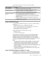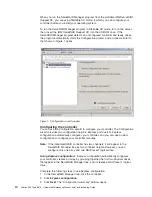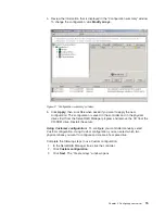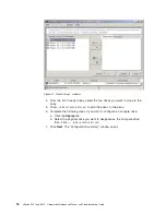
Server controls and indicators
This section identifies the controls and indicators on the front and the back of your
server.
Note:
The illustrations in this document might differ slightly from your hardware.
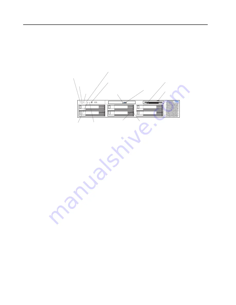
Front view
Power-control
button
Power-on
LED (green)
SCSI or IDE
bus activity LED
(green)
Reset
button
System-error
(amber)
LED
Diskette drive
activity
(green)
LED
Diskette-eject
button
CD-eject button
CD-ROM drive
activity
(green)
LED
System
identification LED
(blue)
Information
(amber)
LED
Hard disk drive
status
(amber)
LED
Hard disk drive
activity
(green)
LED
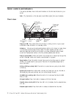
Power-on LED:
This green LED is lit and stays on when you turn on your server
and flashes when the server is in Standby mode.
Attention:
If the power-on light-emitting diode (LED) is off, it does not mean there
is no electrical current present in the server. The LED might be burned out. To
remove all electrical current from the server, you must unplug the server power
cords from the electrical outlets or from the uninterruptible power device.
Power-control button:
Press this button to manually turn on the server and put the
server in Standby mode (see “Server power features” on page 6).
Reset button:
Press this button to reset the server and run the power-on self-test
(POST). You might need to use a pen or the end of a straightened paper clip to
press the button.
SCSI or IDE bus activity LED:
This LED is on when there is activity on the SCSI
or IDE bus.
System-error LED:
This amber LED is lit when a system error occurs. An LED on
the diagnostic LED panel will also be on to further isolate the error.
CD-ROM drive activity LED:
When this LED is lit, it indicates that the CD-ROM
drive is in use.
CD-eject button:
Press this button to release a CD from the drive.
Diskette drive activity LED:
When this LED is lit, it indicates that the diskette drive
is in use.
Diskette-eject button:
Press this button to release a diskette from the drive.
4
xSeries 345 Type 8670: Hardware Maintenance Manual and Troubleshooting Guide
Summary of Contents for eServer xSeries 345 Type 8670
Page 1: ...xSeries 345 Type 8670 Hardware Maintenance Manual and Troubleshooting Guide ERserver...
Page 2: ......
Page 3: ...xSeries 345 Type 8670 Hardware Maintenance Manual and Troubleshooting Guide ERserver...
Page 6: ...iv xSeries 345 Type 8670 Hardware Maintenance Manual and Troubleshooting Guide...
Page 10: ...viii xSeries 345 Type 8670 Hardware Maintenance Manual and Troubleshooting Guide...
Page 18: ...8 xSeries 345 Type 8670 Hardware Maintenance Manual and Troubleshooting Guide...
Page 88: ...78 xSeries 345 Type 8670 Hardware Maintenance Manual and Troubleshooting Guide...
Page 124: ...114 xSeries 345 Type 8670 Hardware Maintenance Manual and Troubleshooting Guide...
Page 130: ...120 xSeries 345 Type 8670 Hardware Maintenance Manual and Troubleshooting Guide...
Page 141: ...Chapter 8 Related service information 131...
Page 142: ...132 xSeries 345 Type 8670 Hardware Maintenance Manual and Troubleshooting Guide...
Page 143: ...Chapter 8 Related service information 133...
Page 144: ...134 xSeries 345 Type 8670 Hardware Maintenance Manual and Troubleshooting Guide...
Page 145: ...Chapter 8 Related service information 135...
Page 146: ...136 xSeries 345 Type 8670 Hardware Maintenance Manual and Troubleshooting Guide...
Page 147: ...Chapter 8 Related service information 137...
Page 157: ...Chapter 8 Related service information 147...
Page 158: ...148 xSeries 345 Type 8670 Hardware Maintenance Manual and Troubleshooting Guide...
Page 159: ...Chapter 8 Related service information 149...
Page 160: ...150 xSeries 345 Type 8670 Hardware Maintenance Manual and Troubleshooting Guide...
Page 161: ...Chapter 8 Related service information 151...
Page 162: ...152 xSeries 345 Type 8670 Hardware Maintenance Manual and Troubleshooting Guide...
Page 166: ...156 xSeries 345 Type 8670 Hardware Maintenance Manual and Troubleshooting Guide...
Page 174: ...164 xSeries 345 Type 8670 Hardware Maintenance Manual and Troubleshooting Guide...
Page 175: ......
Page 176: ...Part Number 48P9718 1P P N 48P9718...


