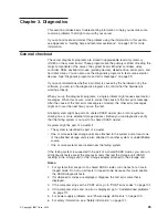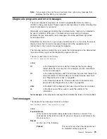
If the diagnostic programs do not detect any hardware errors but the problem
persists during normal server operations, a software error might be the cause. If
you suspect a software problem, see the information that comes with the software
package.
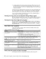
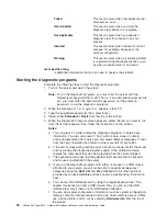
Viewing the test log
When the tests are completed, you can view the test log by selecting
Utility
from
the top of the screen and then selecting
View Test Log
.
Notes:
1. You can view the test log only while you are in the diagnostic programs. When
you exit the diagnostic programs, the test log is cleared (saved test logs are not
affected). To save the test log so that you can view it later, click
Save Log
on
the diagnostic programs screen and specify a location and name for the saved
log file.
2. To save the test log to a diskette, you must use a diskette that you have
formatted yourself; this function does not work with preformatted diskettes. If the
diskette has sufficient space for the test log, the diskette may contain other
data.
Viewing the System Error log
You can also view the System Error log from the diagnostic programs. See the
instructions in “POST error logs” on page 27.
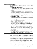
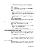
Diagnostic error message tables
For descriptions of the error messages that might appear when you run the
diagnostic programs, see “Diagnostic error codes” on page 88.
Notes:
1. Depending on your server configuration, some of the error messages might not
appear when you run the diagnostic programs.
2. If diagnostic error messages appear that are not listed in the tables, make sure
that your server has the latest levels of BIOS, Advanced System Management
Processor, ServeRAID, and diagnostics microcode installed.
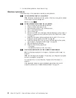
Identifying problems using status LEDs
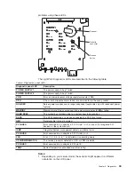
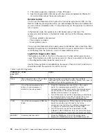
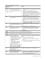
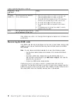
If the system error LED on the front of the server is on, one or more LEDs inside
the server or on the power supply will be on. Your server has LEDs to help you
identify problems with some server components. These LEDs are part of the Light
Path Diagnostics feature built into the server. By following the path of lights, you
can quickly identify the type of system error that occurred.
Your server is designed so that any LEDs that are illuminated remain illuminated
when the server shuts down as long as the ac power source is good and the power
supply can 5 V dc current to the server. This feature helps you isolate the
problem if an error causes the server to shut down. See “Light Path Diagnostics
table” on page 34.
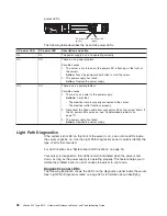
Power supply LEDs
The ac and dc power LEDs on the power supply provide status information about
the power supply. The following illustration shows the location of the ac and dc
Chapter 3. Diagnostics
31
Summary of Contents for eServer xSeries 345 Type 8670
Page 1: ...xSeries 345 Type 8670 Hardware Maintenance Manual and Troubleshooting Guide ERserver...
Page 2: ......
Page 3: ...xSeries 345 Type 8670 Hardware Maintenance Manual and Troubleshooting Guide ERserver...
Page 6: ...iv xSeries 345 Type 8670 Hardware Maintenance Manual and Troubleshooting Guide...
Page 10: ...viii xSeries 345 Type 8670 Hardware Maintenance Manual and Troubleshooting Guide...
Page 18: ...8 xSeries 345 Type 8670 Hardware Maintenance Manual and Troubleshooting Guide...
Page 88: ...78 xSeries 345 Type 8670 Hardware Maintenance Manual and Troubleshooting Guide...
Page 124: ...114 xSeries 345 Type 8670 Hardware Maintenance Manual and Troubleshooting Guide...
Page 130: ...120 xSeries 345 Type 8670 Hardware Maintenance Manual and Troubleshooting Guide...
Page 141: ...Chapter 8 Related service information 131...
Page 142: ...132 xSeries 345 Type 8670 Hardware Maintenance Manual and Troubleshooting Guide...
Page 143: ...Chapter 8 Related service information 133...
Page 144: ...134 xSeries 345 Type 8670 Hardware Maintenance Manual and Troubleshooting Guide...
Page 145: ...Chapter 8 Related service information 135...
Page 146: ...136 xSeries 345 Type 8670 Hardware Maintenance Manual and Troubleshooting Guide...
Page 147: ...Chapter 8 Related service information 137...
Page 157: ...Chapter 8 Related service information 147...
Page 158: ...148 xSeries 345 Type 8670 Hardware Maintenance Manual and Troubleshooting Guide...
Page 159: ...Chapter 8 Related service information 149...
Page 160: ...150 xSeries 345 Type 8670 Hardware Maintenance Manual and Troubleshooting Guide...
Page 161: ...Chapter 8 Related service information 151...
Page 162: ...152 xSeries 345 Type 8670 Hardware Maintenance Manual and Troubleshooting Guide...
Page 166: ...156 xSeries 345 Type 8670 Hardware Maintenance Manual and Troubleshooting Guide...
Page 174: ...164 xSeries 345 Type 8670 Hardware Maintenance Manual and Troubleshooting Guide...
Page 175: ......
Page 176: ...Part Number 48P9718 1P P N 48P9718...

