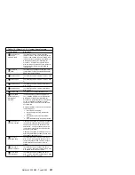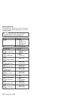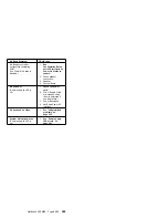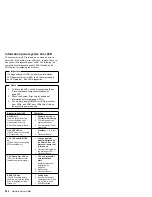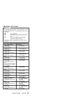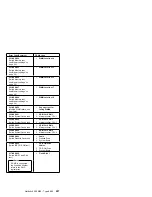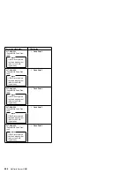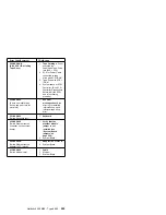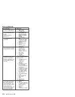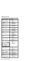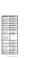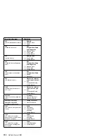
Diagnostic Panel LED
FRU/Action
DASD 2 LED on
(The LED located next to
the drive bay that the failing
drive is installed in will be
turned on.)
1. Failing drive.
2. Be sure the fans are
operating correctly and
the air flow is good.
3. SCSI Backplane
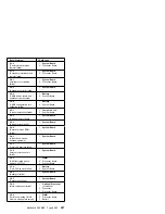
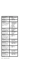
FAN 1 LED on
1. Fan 1
2. Fan Cable
3. System Board
FAN 2 LED on
1. Fan 2
2. Fan Cable
3. System Board
FAN 3 LED on
1. Fan 3
2. Fan Cable
3. System Board
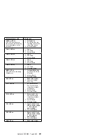
FAN 4 LED on
1. Fan 4
2. Fan Cable
3. Processor Board
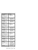
MEM LED on
(The LED next to the failing
DIMM is on.)
1. Failing DIMM in slot
J1, J2, J3, J4, J5, J6,
J7, or J8).
2. Memory Board
3. Processor Board
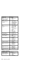
NMI LED on
1. Reboot the system.
2. Check the System
Error Log.
PCI 1 LED on
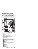
1. PCI Card in slot 5.
See “System board
component locations”
on page 279.
2. System Board
3. Processor Board
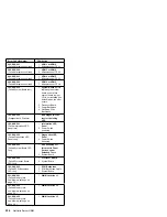
PCI 2 LED on
1. Card in slot 1 to 4
See “System board
component locations”
on page 279.
2. System Board
3. Processor Board
PS1 LED on
1. Check the DC Good
LED on power supply
1. If off, replace
power supply 1.
2. Power Backplane
PS2 LED on
1. Check the DC Good
LED on power supply
2. If off, replace
power supply 2.
2. Power Backplane
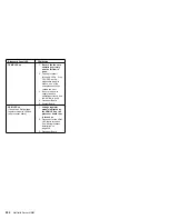
SMI LED on
1. Reboot the system.
Netfinity 5500 M20 - Type 8662
291
Summary of Contents for 866251Y - Netfinity 5500 M20
Page 2: ......
Page 8: ...vi Netfinity Server HMM...
Page 336: ...32 33 33 34 35 36 37 38 39 40 41 42 43 328 Netfinity Server HMM...
Page 346: ...338 Netfinity Server HMM...
Page 354: ...346 Netfinity Server HMM...
Page 355: ...Related service information 347...
Page 356: ...348 Netfinity Server HMM...
Page 357: ...Related service information 349...
Page 368: ...360 Netfinity Server HMM...
Page 369: ...Related service information 361...
Page 385: ......
Page 386: ...IBM Part Number 09N1015 Printed in U S A S37L 2 2 1...

