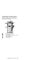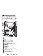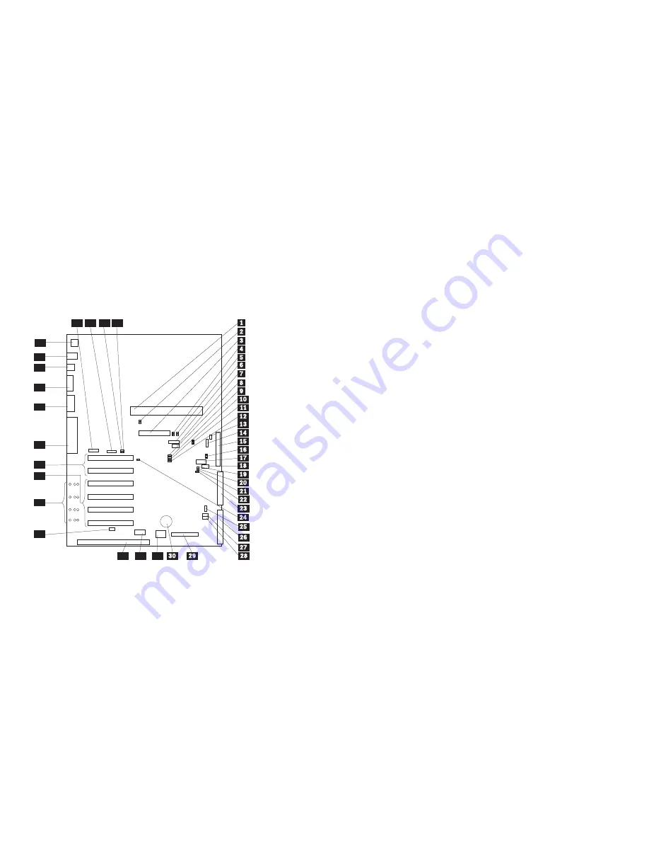
System board component locations
The following illustration shows a layout of the system
board and identifies system board components. You might
need to refer to this figure before you install hardware in
the server, or when you record information in the tables in
this chapter. You might also need to refer to this figure
when you set configuration jumpers on the system board.
33
34
37
32
35
38
31
36
39
40
41
42
43
44
46
47
45
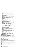
.1/
Processor board connector (J19)
.2/
Advanced System Management Processor error
LED (CR24)
.3/
RAID channel 1 connector (J7)
.4/
RAID channel 1 error LED (CR30)
.5/
RAID channel 2 error LED (CR31)
.6/
Reserved (J54)
.7/
Reserved (J64)
.8/
Disable RAID controller jumper block (J11)
.9/
Reserved (J45)
.1ð/
Power-on control jumper block with cable (J32)
.11/
RAID download jumper block (J15)
.12/
Reserved (J25)
.13/
Reserved (J9)
.14/
Power backplane cable connector (J8)
.15/
RAID channel 2 connector (to backplane) (J3)
.16/
RAID system error LED (CR32)
.17/
RS-485 connector (J27)
.18/
Reserved (J35)
.19/
SCSI activity LED connector (J52)
.2ð/
Reserved (J34)
.21/
Reserved (J29)
Netfinity 5500 M20 - Type 8662
279
Summary of Contents for 866251Y - Netfinity 5500 M20
Page 2: ......
Page 8: ...vi Netfinity Server HMM...
Page 336: ...32 33 33 34 35 36 37 38 39 40 41 42 43 328 Netfinity Server HMM...
Page 346: ...338 Netfinity Server HMM...
Page 354: ...346 Netfinity Server HMM...
Page 355: ...Related service information 347...
Page 356: ...348 Netfinity Server HMM...
Page 357: ...Related service information 349...
Page 368: ...360 Netfinity Server HMM...
Page 369: ...Related service information 361...
Page 385: ......
Page 386: ...IBM Part Number 09N1015 Printed in U S A S37L 2 2 1...

