84
7.3 Electrical installation
Caution
Danger from electric current. The electrical installation
is to be carried out only by a qualified electrician!
■
Comply with all relevant legislation (e.g. EN 60204-1).
■
For long supply lines, select cable diameters in accord-
ance with the technical regulations.
■
Carry out electrical installation in accordance with the
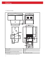
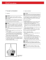
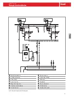
wiring diagram (for wiring within the unit, see Fig. D7).
■
Install the system bus for the control systems separately
from the mains cable.
■
Establish plug connections from the Air-Injector to the
combi box and from the combi box (inside) to the roof unit.
■
Wire the actuator of the ER/bypass damper 2 to the
DigiUnit terminal box.
■
Wire the mixing valves to the connection box. (There is a
plug connection for Hoval magnetic mixing valves.)
■
For injection system: Wire pump to the DigiUnit terminal
box.
■
Make sure there is onsite overload protection equipment
for the mains connection line of the zone control panel
(short circuit resistance 10 kA).
DigiUnit terminal box with
isolation switch
Actuator of ER/bypass damper 2
Plug connection, actuator
Cable feedthroughs and plug
connections, Air-Injector
Power supply
Bus cable
Connection box
Fig. D7: Wiring in unit
RoofVent
®
twin heat
Transport and installation
Summary of Contents for RoofVent CON-9
Page 2: ......
Page 4: ...2...
Page 6: ...4...
Page 8: ...6...
Page 12: ...10 RoofVent LHW Use...
Page 40: ...38 RoofVent LKW Use...
Page 68: ...66 RoofVent twin heat Use...
Page 94: ...92 RoofVent twin cool Use...
Page 122: ...120 RoofVent twin pump Use...
Page 150: ...148...
Page 154: ...152 RoofVent condens Use...
Page 180: ...210 RoofVent LH Construction and operation...
Page 208: ...238 RoofVent LK Use...
Page 256: ...286...
Page 268: ...298...
Page 274: ...304...
Page 279: ......


