68
ch1
throttle
(throttle curve)
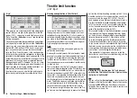
This display refers only to the control curve of the thrott-
le servo.
The throttle curve can also be defi ned using up to
fi ve points, in a similar way to the collective pitch
curve (see previous page).
• In all cases the throttle must be fully open at the end-
point of the throttle / collective pitch stick (exception:
autorotation – see page 74).
• The hover point is normally located at the centre of
the stick travel, and the throttle setting should be ad-
justed relative to the collective pitch curve in such a
way that the correct system rotational speed is obtai-
ned at this point.
• At the minimum position of the throttle / collective
pitch stick the throttle curve should be set up so that
the motor runs at a distinctly higher speed compared
to the idle setting, with the clutch reliably engaged.
In all fl ight phases the motor is started and stopped
using the throttle limiter (see below).
If you are used to a different radio control system which
uses two separate fl ight phases for this – “with idle-up”
and “without idle-up” – please note that the throttle limit-
er renders this complication superfl uous.
Ensure that the throttle limiter is closed before you start
the motor, i.e. the throttle can only be adjusted within its
idle range using the idle trim. Be sure to read the safe-
ty notes on page 72 which refer to this. If the idle is set
too high when you switch the transmitter on, you will see
and hear a clear warning!
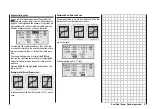
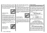
The following three diagrams show typical 3-point thrott-
le curves for different fl ight phases, such as hover, aero-
batics and 3-D fl ying.
Typical throttle curves for different fl ight phases:
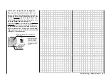
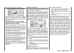
Notes on using the “Throttle limit” function:
We strongly recommend that you make use of the thrott-
le limit function (»
Control settings
« menu, page 54).
When you use this function the throttle servo is com-
pletely disconnected from the throttle / collective pitch
stick when the rotary proportional control (CTRL 7) is at
its bottom end-point; the motor runs at idle and only re-
sponds to the Ch1 trim. This feature enables you to start
the motor from within any fl ight phase. Once the motor
is running, turn the rotary control to the opposite end-
point, so that full control of the throttle servo is returned
to the throttle / collective pitch stick. It is important that
the throttle limiter should not restrict the throttle servo at
its top end-point; you can avoid this by setting the con-
trol travel to 125% in the “Lim” line of the »
Control set-
tings
« menu.
H o v e r
A e r o b a t i c s
3 D - F l y i n g
1 2 3 4 5
C o n t r o l T r a v e l
1 2 3 4 5
C o n t r o l T r a v e l
1 2 3 4 5
C o n t r o l T r a v e l
O
u
tp
u
t
+ 1 0 0 %
- 1 0 0 %
O
u
tp
u
t
+ 1 0 0 %
- 1 0 0 %
O
u
tp
u
t
+ 1 0 0 %
- 1 0 0 %
Heli mixer – Model helicopter
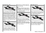
Note:
Releasing the full throttle range, and imposing the thrott-
le limiter again, trips the switching threshold of the con-
trol switch “G3” (i.e. in either direction); this switch can
be used for automatically starting and stopping the stop-
watch to record the fl ight time, or some similar purpose;
see page 54.
When you select autorotation, the mixer automati-
cally switches the value to a variable pre-set value;
see page 74.
Summary of Contents for MX-16S
Page 1: ...1...
Page 17: ...17...
Page 31: ...31 Fixed wing models Installation and connections...
Page 35: ...35 Program description Reserving a new memory...
Page 47: ...47 Base settings Model helicopter...
Page 83: ...83 Fail safe...
Page 89: ...89 Programming examples Fixed wing model...
Page 109: ...109 Programming examples Model helicopter...
Page 112: ...112 112...
Page 116: ...116...

