27
Description of transmitter – Servo display
Servo display
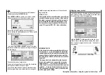
Pressing the
SELECT
button at the transmitter’s basic
display calls up a visual representation of the current
servo positions on the transmitter screen.
This display shows the current position of every ser-
vo in the form of a bar diagram, taking into account the
transmitter control and servo settings, the Dual Rate /
Expo functions, the inter-action of all active mixers etc.
The display is accurate, and covers the range -150% to
+150% of normal travel. 0% means the exact centre po-
sition. This allows you to check your settings quickly wi-
thout even having to switch the receiver on. However,
this does not mean that you don’t need to bother che-
cking all the programming steps on the model; you must
do this carefully before operating it for the fi rst time, as
this is the only reliable method of picking up and correc-
ting errors.
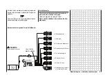
For fi xed-wing model aircraft the display shows the
information arranged in the following way:
Bar 1 = Throttle / brake servo
Bar 2 = Aileron or left aileron
Bar 3 = Elevator
Bar 4 = Rudder
Bar 5 = Right aileron
Bar 6 = Left camber-changing fl ap / free channel
Bar 7 = Right camber-changing fl ap / free channel
Bar 8 = Free channel
… and for model helicopters:
Bar 1 = Collective pitch or roll (2) or nick (2)
servo
Bar 2 = Roll (1) servo
Bar 3 = Nick (1) servo
Bar 4 = Tail rotor servo (gyro)
Bar 5 = Nick (2) servo / free channel
Bar 6 = Throttle servo or speed controller
Bar 7 = Gyro gain / free channel
Bar 8 = Speed controller / free channel
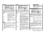
Holding the
SELECT
button held in while you are at the
transmitter’s basic display calls up a visual display of the
current positions of the two INC / DEC buttons (CTRL
5 + 6). This display disappears again when you release
the
SELECT
button. At the same time a small symbol
appears on the left, adjacent to the channel display:
When you hold the
SELECT
button pressed in, the po-
sition display on the basic transmitter display, consisting
of the two central vertical bars, also changes: it switches
from a display of the current trim position to the current
position of the INC / DEC buttons, CTRL 5 + 6.
As you would expect, the left-hand bar represents the
position of the INC / DEC button CTRL 6, located to the
left of the aerial base, and the right-hand bar shows the
position of CTRL 5 (however, both horizontal bars con-
tinue to show the current position of the corresponding
transmitter stick trim levers):
As soon as you release the
SELECT
button, the screen
reverts to a display of the current trim position of the
four trim levers of the two dual-axis stick units; see pic-
ture left.
Position display
INC / DEC button, CTRL 5 + 6
Summary of Contents for MX-16S
Page 1: ...1...
Page 17: ...17...
Page 31: ...31 Fixed wing models Installation and connections...
Page 35: ...35 Program description Reserving a new memory...
Page 47: ...47 Base settings Model helicopter...
Page 83: ...83 Fail safe...
Page 89: ...89 Programming examples Fixed wing model...
Page 109: ...109 Programming examples Model helicopter...
Page 112: ...112 112...
Page 116: ...116...


