41
Base settings – Fixed-wing model
Phase 2 / Phase 3
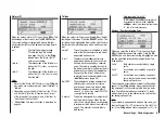
When you select »Phase 2« or »Phase 3«, you will see
SEL
at the bottom edge of the screen. Press the
SE-
LECT
button, and the current setting is shown highligh-
ted. If you do not wish to use the default names, use
the right-hand rocker button to select a suitable name
from the pre-sets. Press
SELECT
to return to the func-
tion line.
Move to the switch symbol
using the right-hand ro-
cker button, then press
SELECT
again. A switch can be
assigned to the fl ight phase as described on page 25.
For more information on fl ight phase programming ple-
ase refer to page 60, in the section entitled »
Phase
trim
«.
Trainer / Student
In this menu line you can assign a “transfer switch” for
Trainer (teacher / pupil) mode operations, after pressing
SELECT
or
ENTER
, as described on page 25.
For more information on Trainer systems please refer to
page 110.
*
GRAUPNER does not guarantee that GRAUPNER radio control sys-
tems will work correctly in conjunction with receiving systems and
radio control equipment made by other manufacturers.
Receiver output
For maximum fl exibility in terms of receiver socket as-
signment, the mx-16s program provides the means to
swap over the servo outputs 1 to max. 8; this is carried
out on the second page of the »Receiv out.« sub-menu.
Press the
SELECT
or
ENTER
button to move to the
next page of the display. Here you can assign the “con-
trol channels” for servos 1 … 8 to any receiver out-
put you wish to use. However, please note that the dis-
play in »
Servo
display
« – which you can reach by pres-
sing
SELECT
from the basic display – refers exclusively
to the
“control channels”
, i.e. the outputs are
not
swap-
ped over.
With the
SELECT
button held pressed in, use the right-
hand rocker button to select the servo / output combina-
tion you wish to change, then press
ENTER
or
SELECT
.
Now you can assign the desired servo(s) to the selected
output using the right-hand rocker button … or alterna-
tively press
CLEAR
to revert to the default sequence.
Please note that any changes to servo settings, such
as servo travel, Dual Rate / Expo, mixers etc.,
must be
carried out according to the original (default) recei-
ver socket sequence.
Typical applications:
• If you wish to use a smaller receiver with six or even
just four servo sockets, it may be necessary to swap
over the receiver sockets in order to be able to opera-
te a second camber-changing fl ap, a second aileron
servo or a speed controller.
• It may also prove necessary to swap servos for Trai-
ner mode operations, if you are using a model set up
for another make * of equipment, to avoid having to
re-connect the servos at the receiver.
Note:
Please note that the Fail-safe “hold-mode” and “position”
programming in SPCM mode always affect the “outputs”,
i.e. the receiver socket numbers; this still applies if you
swap the receiver outputs.
Summary of Contents for MX-16S
Page 1: ...1...
Page 17: ...17...
Page 31: ...31 Fixed wing models Installation and connections...
Page 35: ...35 Program description Reserving a new memory...
Page 47: ...47 Base settings Model helicopter...
Page 83: ...83 Fail safe...
Page 89: ...89 Programming examples Fixed wing model...
Page 109: ...109 Programming examples Model helicopter...
Page 112: ...112 112...
Page 116: ...116...


