63
brak
fl ap
(Brake
fl ap)
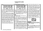
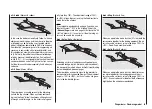
When you operate the brake function (C1 stick) both fl ap
servos move together for the landing approach; the mi-
xer ratio can be set to any value in the range -150% to
+150%. Down-fl ap is usually selected.
brak
aile
(Brake
aileron)
When you operate the brake function, both aileron ser-
vos move together for the landing approach; the mi-
xer ratio can be set to any value in the range -150% to
+150%. It can also be useful to defl ect both ailerons up
slightly
when the airbrakes are extended.
ail
rudd
(Aileron
rudder)
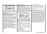
In this case the rudder automatically “follows” when an
aileron command is given, and the mixer ratio (degree
of following) can be set by the user. Coupled aileron /
rudder (sometimes abbreviated to CAR; also known as
“combi-switch”) is especially useful for suppressing ad-
verse yaw in conjunction with aileron differential, and
this combination usually makes smooth turns very easy
to fl y. Naturally, the rudder can still be controlled sepa-
rately by means of its dedicated stick. If an (optional)
switch (SW 1 … 4) is assigned to this function, the mixer
can be switched on and off in fl ight, so that you can con-
trol the ailerons and rudder separately if and when you
so desire.
ail
fl aps
(Aileron
fl ap)
This mixer feeds a variable amount of the aileron sig-
nal into the fl ap channel. When an aileron command
is given, the fl aps “follow” the ailerons, although usual-
ly through a smaller angle, i.e. the mixer ratio is gene-
rally less than 100%. The adjustment range of -150%
to +150% allows the user to set up the fl ap direction to
match that of the ailerons.
Note:
If your model is equipped with only one fl ap servo, you
should still select “... 2FL” in the “aile/fl ap” line of the
»
Base settings
« menu (see page 39) but leave the “Ail
Flap” mixer at 0%. In contrast, all the other wing mi-
xers can be used in the usual way.
brak
elev
(Brake
elevator)
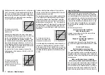
Extending any form of airbrakes usually generates an
unwanted change in pitch trim (nose up or nose down);
this is especially marked when a butterfl y (crow) braking
system is deployed (see next page).
This mixer feeds a corrective signal to the elevator to
compensate for this unwanted moment. The adjustment
range is -150% to +150%, but “usual” values are gene-
rally in the low double fi gures.
Wing mixers – Fixed-wing model
Summary of Contents for MX-16S
Page 1: ...1...
Page 17: ...17...
Page 31: ...31 Fixed wing models Installation and connections...
Page 35: ...35 Program description Reserving a new memory...
Page 47: ...47 Base settings Model helicopter...
Page 83: ...83 Fail safe...
Page 89: ...89 Programming examples Fixed wing model...
Page 109: ...109 Programming examples Model helicopter...
Page 112: ...112 112...
Page 116: ...116...

