76
General notes regarding freely programmable mixers
The two menus »
Wing mixers
« and »
Heli mixer
«, as
described on the preceding pages, contain a wide range
of ready-programmed coupling functions. The basic me-
aning of mixers has already been explained on page 61,
together with the principle on which they work. In the fol-
lowing section you will fi nd more general information re-
lating to “free mixers”:
In addition to the pre-programmed mixers mentioned
above, the mx-16s offers three freely programmable mi-
xers which can be used in every model memory; their in-
puts and outputs can be selected to suit your exact re-
quirements.
Any
control function
(transmitter control 1 to 8) can be
assigned as the input signal of a “free mixer”. Alterna-
tively any switch can be assigned as the input signal
using what is termed the “switch channel” (see below).
The control function itself consists of the transmitter con-
trol signal and any control characteristics as defi ned, for
example, in the »
Dual Rate / Expo
« and »
Control set-
tings
« menus.
The mixer output acts upon a freely selectable control
channel (1 to max. 8 – depending on receiver type). Be-
fore the signal is passed to the associated servo, the
only infl uences which can act upon it are those defi ned
in the »
Servo settings
« menu, i.e. the servo reverse,
neutral point offset and travel functions.
One
control function
can be set up to affect several mi-
xer inputs simultaneously, if, for example, several mixers
are to be arranged to work in parallel.
Conversely it is possible for several mixer outputs to af-
fect one and the same
control channel
.
The following description of the free mixers includes ex-
amples of such arrangements.
In software terms the default setting for any freely pro-
grammable mixer is that it is constantly switched on, but
it is also possible to assign an optional ON / OFF switch
to it. However, since there are so many functions to
which switches can potentially be assigned, you should
take care not to assign a confusing number of functions
to any particular switch.
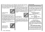
The two important mixer parameters are as follows:
• …
the
mixer ratio
, which defi nes the extent to which
the input signal acts on the output of the control
channel which is programmed as the mixer output.
• …
the
neutral point
, which is also termed the “off-
set”. The offset is that point on the travel of a trans-
mitter control (stick, rotary proportional knob CTRL 7
or INC / DEC buttons CTRL 5 / 6) at which the mixer
has no infl uence on the control channel which is de-
fi ned as its output. Normally this is the centre point of
the transmitter control, but the offset can be placed at
any point on the control’s travel.
Switch channel “S” as mixer input
In some cases a constant control signal is all that is re-
quired as the mixer input; a typical application would be
for slight up-elevator trim when an aero-tow coupling is
closed – independent of the normal elevator trim. If you
then assign a switch, you can switch to and fro between
the two mixer end-points, and adjust the supplementary
elevator trim defl ection by altering the mixer input.
To identify this special arrangement, this mixer input
control function in the program is designated “S” for
“switch channel”. If you do not want the mixer output to
be affected by the standard transmitter control, the con-
trol can be de-coupled from the function input of the “re-
ceiving” control channel by entering “free” in the »
Cont-
rol settings
« menu; see pages 50 and 52. The following
menu description includes an example which will make
this function clear.
Free mixers
Summary of Contents for MX-16S
Page 1: ...1...
Page 17: ...17...
Page 31: ...31 Fixed wing models Installation and connections...
Page 35: ...35 Program description Reserving a new memory...
Page 47: ...47 Base settings Model helicopter...
Page 83: ...83 Fail safe...
Page 89: ...89 Programming examples Fixed wing model...
Page 109: ...109 Programming examples Model helicopter...
Page 112: ...112 112...
Page 116: ...116...


