93
you should be careful only to use the change-over
switch at the “motor OFF” setting.
To conclude the programming procedure, move the se-
lected “change-over switch” back to the “motor ON” posi-
tion, i.e. “forward”; move back to the multi-function menu
and from there to the menu …
»Wing mixers«
(page 61 ... 65)
… where you can – assuming that you have not alrea-
dy done this in your general model programming – se-
lect the “
Brake
aileron
” line and set the desired aile-
ron travel when the C1 stick is operated in the up direc-
tion (“Brake”). In the
column press
SELECT
, then
assign your selected “change-over switch” by moving the
switch from “front” to “rear”.
If your model also features camber-changing fl aps,
and you have therefore selected “
2AIL 2F
L” in the “
Ai-
leron / fl ap
” line of the »
Base settings
« menu, locate
the “change-over switch” you have just operated (in this
case switch 1), move it “forward” again and switch to the
“
Brake
fl ap
” line using the right-hand rocker button,
whilst holding the
SELECT
button pressed in. You can
now set the desired down-defl ection of the fl aps when
the C1 stick is moved (this fl ap position is termed “crow”
or “butterfl y”; see also page 64), and assign the external
switch which also acts as the change-over switch, as al-
ready described.
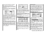
If you now switch back to the »
Servo display
« menu
and move just the C1 stick, you will see that the bar
display for Channel 1 either remains at around -100%
while the displays for channels 2 + 5 (and also the fl aps
6 + 7, if set up) follow the stick movement, or the other
way round: when the switch is operated, the latter stay
at around the middle, and only the Channel 1 display
moves.
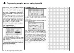
SYM
and
ASY
fi elds are now replaced by
STO
and
CLR
. With the
STO
button highlighted, move the C1
stick to the “front” end-point and press the
SELECT
but-
ton: the value to the right of “Offs” now changes from
0% to approx. +100% and the graphic display of the mi-
xer characteristic line displayed on the right also chan-
ges accordingly:
Return to the basic display by pressing
ESC
, then press
SELECT
to move to the menu …
»Servo display«
(page 27)
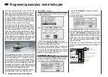
… where you can immediately check the effect of the
settings you have entered so far: with the mixer switched
off, the bar display for Channel 1 follows the movement
of the C1 stick. With the mixer switched on it stops – as
shown – at around -100%.
Note:
If you carry out this test with the receiving system
and power system switched on, please take great
care that you operate the change-over switch only
in the “motor OFF” position! If you ignore this, the-
re is a danger that the power system will be sever-
ely overloaded by being switched on abruptly, and
it could even suffer damage. For the same reason
Programming examples: Fixed-wing model
Summary of Contents for MX-16S
Page 1: ...1...
Page 17: ...17...
Page 31: ...31 Fixed wing models Installation and connections...
Page 35: ...35 Program description Reserving a new memory...
Page 47: ...47 Base settings Model helicopter...
Page 83: ...83 Fail safe...
Page 89: ...89 Programming examples Fixed wing model...
Page 109: ...109 Programming examples Model helicopter...
Page 112: ...112 112...
Page 116: ...116...


