


In SINGLE SWEEP mode, the scope will trigger
one time for each softkey press, subject to the
trigger level setting (triggering always occurs on
the rising portion of the applied waveform).
Messages on the line just above the softkeys
indicate the status of the single sweep. The single
sweep is useful in measuring one-time events,
such as a tone burst at the beginning of a
transmission. Such bursts may be followed by
other modulation which would over-write the
screen if measured in the NORMAL trigger
mode.
Level
Adjust the TUNING knob to select the desired
trigger level. The trigger level is a relative level
setting between the values of 0 and 999 (full
scale) where 0 is the most negative and 999 is the
most positive voltage.
NOTE
To achieve the fastest update rate of the
display a trigger level setting of 500 is
recommended for most applications.
Horiz
Press the desired softkey to select the Horizontal
Sweep rate (20 us to 1 sec/div). Since all ranges
cannot be shown on one screen, press the
more
softkey for additional selections.
NOTE
If horizontal sweep rates of greater than 10
msec/div are selected, the update rate will
slow down. A good overall setting for most
applications is 200 usec per division.
Horizontal Position
Adjust the horizontal position through the (
)
cursor field either by using the desired softkey
(MOVE LEFT, MOVE RIGHT) or by using the
rotary TUNING knob.
Vertical Sensitivity
Press the desired softkey to select the Vertical
Sensitivity (AM: 1%, to 50% per division, FM:
100 Hz to 50 kHz per division, dependent on
bandwidth selected). When all ranges cannot be
shown on one screen, press the more softkey for
additional selections.
NOTE
The vertical scales and softkeys for FM devia-
tion will change automatically between wide-
band and narrowband.
Vertical Position
Adjust the vertical position through the
cursor field either by using the desired softkey
(MOVE UP, MOVE DOWN) or by using the
rotary TUNING knob.
Press the expand softkey from any field in the
scope display window to enlarge the display for
more detailed analysis. Use the return softkey to
get back to the normal size display.
NOTE
Scale and positioning adjustments are not
possible for stored waveforms that are
displayed through the use of single sweep or
triggering on single non-periodic signals.
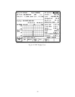
Marker (if equipped)
Select marker operation by moving the cursor to
the "Mrk:" field, then pressing the desired softkey
(
V,
T, or 1/
T). Selection provides two
markers on the Modulation Scope screen (refer to
figure 3-21). Function of the "toggle marker"
softkey and Tuning Knob for positioning of
markers is similar to that described in section
3-7.2.1.
V -
This softkey selection provides markers that are
horizontally located to permit relative readings
along the scope vertical axis. The display
adjacent to the "Mrk:" field shows the relative
vertical deflection between the two marker
positions.
53
Summary of Contents for R2600 Series
Page 8: ...3 7 1 3 AC DC Voltmeter 41 3 7 1 4 INT DIST EXT DIST Meter 43 v...
Page 46: ...This Page Intentionally Left Blank xxxvi...
Page 66: ...DISPLAY ZONE RF ZONE AUDIO ZONE Figure 3 1 Screen Zone Arrangement 20...
Page 68: ...Figure 3 2 System Help 22...
Page 83: ...Figure 3 11 General Sequence Mode Select 37...
Page 85: ...39 Figure 3 12 RF Display Zone...
Page 88: ...Figure 3 14 Digital Voltmeter Screens 42...
Page 102: ...Figure 3 22 Bar Graphs 56...
Page 107: ...Figure 3 24 Memory Screens 61...
Page 128: ...This Page Intentionally Left Blank 82...
Page 202: ...This Page Intentionally Left Blank 156...
Page 205: ...Figure 11 1 R 2670 with SECURENET Option Housing 159...
Page 206: ...This Page Intentionally Left Blank 160...
Page 218: ...Figure 13 8 Test Key Programming Display Figure 13 9 External Key Programming Display 172...
Page 225: ...Figure 13 12 Duplex Mode Display Zone 179...
Page 234: ...VOICE Figure 13 17 CLEAR SCOPE Markers 188...
Page 236: ...This Page Intentionally Left Blank 190...
Page 249: ...Figure 14 8 SECURENET CLEAR SCOPE Display of Output Modulation 203...
Page 252: ...This Page Intentionally Left Blank 206...
Page 256: ...210 This Page Intentionally Left Blank...
Page 267: ...Figure 17 7 Encryption Select Display Figure 17 7 Encryption Select Display 221 221...
Page 286: ...This Page Intentionally Left Blank 240...
Page 291: ...Figure 18 1 Radio BER Test Mode Audio Zone Figure 18 2 Radio BER Test Mode BER Meter 245...
Page 293: ...Figure 18 4 Receive BER 247...
Page 298: ...Figure 18 6 ASTRO CLEAR SCOPE Display of Output Modulation 252...
Page 304: ...Figure 21 1 PROJ 25 Version Screen Figure 21 2 PROJ 25 Options Screen 258...
Page 309: ...Figure 21 6 SET UP Display Screen Figure 21 7 Encryption Select Display 263...
Page 335: ...Figure 22 4 PROJ 25 CONV CLEAR SCOPE Display of Output Modulation 289...
Page 339: ...Figure 24 1 PROJ 25 Version Screen Figure 24 2 PROJ 25 Options Screen 293...
Page 354: ...Figure 25 3 Encryption Select Display Figure 25 4 Algorithm Select Display 308...
Page 369: ...B 6 This Page Intentionally Left Blank...
Page 379: ...This Page Intentionally Left Blank F 4...
Page 383: ...This Page Intentionally Left Blank H 2...
Page 389: ...J 4 This Page Intentionally Left Blank...
Page 393: ...This Page Intentionally Left Blank K 4...