


and other sections in this manual for more details
about the analyzer's Monitor functions.
NOTE
Do not directly apply excessive input power to
the ANT port. In the event that excessive RF
power is inadvertently applied, the port is
protected by in-line RF fuse. This fuse may be
accessed by unscrewing the front of the BNC
connector out of the front panel. Refer to
paragraph 12-2.4 under the General
Operations tab of this manual.
14-1.3
Generate Mode Testing
To setup for Generate mode testing, put the
analyzer in SECURENET mode, and in the RF
zone select Generate mode. Select the desired
settings for each cursor position in the RF zone.
Also select the desired levels in the Audio zone for
the summed modulating signal and SECURENET
deviation. Remember to enable the switches. To
transmit anything other than BER, the Generate
code in the Audio zone must be set to voice frame.
In the RF zone, select the appropriate softkey for
the Gen RF Out cursor location. There are two
choices: GEN and RF I/O port. The RF I/O port is
recommended for most applications where GEN
and MON ports are combined for a single
connection to the radio under test. The GEN port is
recommended where higher levels of output signal
are needed. Connect a coaxial cable from the
selected output port to the input of the radio. See
the General Operations tab and other sections in
this manual for more details about the analyzer's
Generate functions.
NOTE
Do not apply input power to the GEN output
port. In the event RF power is inadvertently
applied, the port is protected by in-line RF
fuse. This fuse may be accessed by unscrewing
the front of the BNC connector out of the front
panel. Refer to paragraph 12-2.4 under the
General Operations tab of this manual.
14-2 BER TESTING THE RADIO RECEIVER
(Generate Mode)
14-2.1
Radio in BER Test Mode
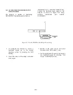
This application example describes the receiver test
for radios that have BER test capability. The
receiver must have the capability of receiving an
unencrypted V.52 BER test pattern. Performance
of this test requires the analyzer to operate in
Generate BER Test mode. In this mode the
analyzer generates a test signal and the radio
monitors the test signal. When testing the receiver,
the radio under test measures the BER of the
received signal and displays the result to the
operator. The output level of the analyzer is
reduced until the radio BER threshold is
determined. Consult the radio maintenance manual
to determine the BER threshold percentage to be
used in testing.
Test frequencies may be specified for BER test of
your equipment. Consult the radio maintenance
manual.
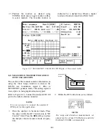
1. Connect the RF Input port of the radio
under test to the GEN OUT port of the
analyzer. Consult the radio maintenance
manual to determine the appropriate test
port.
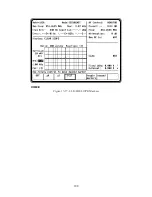
2. Select the SECURENET BER Test mode by
placing the cursor in the “Code:” field in the
Audio Zone (figure 14-1). With the cursor
in the “Code:” field, select the BER softkey.
3. Set controls in the Audio zone as follows.
Fixed 1kHz:
0.000 V
Code
BER
External:
0.000 V
x
x
Securenet:
x.xx kH z ~
SECURENET 04.0 kHz
192
Summary of Contents for R2600 Series
Page 8: ...3 7 1 3 AC DC Voltmeter 41 3 7 1 4 INT DIST EXT DIST Meter 43 v...
Page 46: ...This Page Intentionally Left Blank xxxvi...
Page 66: ...DISPLAY ZONE RF ZONE AUDIO ZONE Figure 3 1 Screen Zone Arrangement 20...
Page 68: ...Figure 3 2 System Help 22...
Page 83: ...Figure 3 11 General Sequence Mode Select 37...
Page 85: ...39 Figure 3 12 RF Display Zone...
Page 88: ...Figure 3 14 Digital Voltmeter Screens 42...
Page 102: ...Figure 3 22 Bar Graphs 56...
Page 107: ...Figure 3 24 Memory Screens 61...
Page 128: ...This Page Intentionally Left Blank 82...
Page 202: ...This Page Intentionally Left Blank 156...
Page 205: ...Figure 11 1 R 2670 with SECURENET Option Housing 159...
Page 206: ...This Page Intentionally Left Blank 160...
Page 218: ...Figure 13 8 Test Key Programming Display Figure 13 9 External Key Programming Display 172...
Page 225: ...Figure 13 12 Duplex Mode Display Zone 179...
Page 234: ...VOICE Figure 13 17 CLEAR SCOPE Markers 188...
Page 236: ...This Page Intentionally Left Blank 190...
Page 249: ...Figure 14 8 SECURENET CLEAR SCOPE Display of Output Modulation 203...
Page 252: ...This Page Intentionally Left Blank 206...
Page 256: ...210 This Page Intentionally Left Blank...
Page 267: ...Figure 17 7 Encryption Select Display Figure 17 7 Encryption Select Display 221 221...
Page 286: ...This Page Intentionally Left Blank 240...
Page 291: ...Figure 18 1 Radio BER Test Mode Audio Zone Figure 18 2 Radio BER Test Mode BER Meter 245...
Page 293: ...Figure 18 4 Receive BER 247...
Page 298: ...Figure 18 6 ASTRO CLEAR SCOPE Display of Output Modulation 252...
Page 304: ...Figure 21 1 PROJ 25 Version Screen Figure 21 2 PROJ 25 Options Screen 258...
Page 309: ...Figure 21 6 SET UP Display Screen Figure 21 7 Encryption Select Display 263...
Page 335: ...Figure 22 4 PROJ 25 CONV CLEAR SCOPE Display of Output Modulation 289...
Page 339: ...Figure 24 1 PROJ 25 Version Screen Figure 24 2 PROJ 25 Options Screen 293...
Page 354: ...Figure 25 3 Encryption Select Display Figure 25 4 Algorithm Select Display 308...
Page 369: ...B 6 This Page Intentionally Left Blank...
Page 379: ...This Page Intentionally Left Blank F 4...
Page 383: ...This Page Intentionally Left Blank H 2...
Page 389: ...J 4 This Page Intentionally Left Blank...
Page 393: ...This Page Intentionally Left Blank K 4...