


field (29 being the most recent), and the selected
frame will be displayed.
To reset the "Frame:" and "Frame Counter:" fields,
press the
frame
reset
softkey.
The "Raw:" field displays the captured link control
format data for a single frame in hex format.
18-3 ASTRO RADIO RECEIVE TESTS
This section describes the basic test setup for testing
ASTRO radio received voice and embedded data. If
the selected radio channel is encrypted, select the
analyzer encryption algorithm and key as described
in section 17-7. Place the analyzer in Generate mode
as shown in the example below: Select the
appropriate frequency that matches the radio under
test; 806.0625 MHz is used in this example.
1. Place the cursor in the RF Zone and
configure each filed as follows:
RF Control:
Freq:
Preset:
806.0625 MHz
RF I/O
B/W:NB
GENERATE
Output Level
-50.0 dBm
Gen RF Out
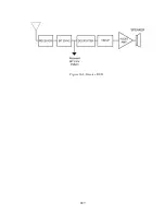
2. Connect the RF input/output of the radio
under test to the RF I/O port of the analyzer
as shown in figure 17-4.
3. Press the
AUD
hardkey to place the cursor
in the Audio Zone and make the selections
shown below. External must be set to a
value and turned on with ~ to enable the
input from the microphone of the analyzer.
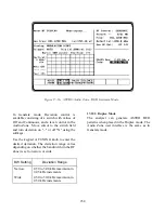
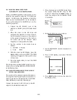
4. Place the cursor on VOICE FRAME in the
Audio Zone, and press the
display table
softkey. The VOICE FRAME ENCODE
screen shown in figure 17-14 will be
displayed.
5. Insert the desired values into each field of the
VOICE FRAME ENCODE table or press the
default frame
softkey to enter pre-
programmed values. It is essential to enter the
correct Network ID code that matches the
radio. This can be determined from the
VOICE FRAME DECODE table when
monitoring the transmitted voice frames from
the radio (refer to section 18-2).
6. Press the
return
softkey from the VOICE
FRAME ENCODE screen.
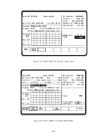
7. Press the
DISP
hardkey then move the
cursor to the "Display:" field and select the
CLEAR SCOPE
softkey.
8. Connect a microphone to the analyzer and
press the PTT. Note, when the microphone
PTT is pressed, the ASTRO modulated
waveform appears on the scope in the Display
Zone. Turn on the radio and talk into the
microphone of the analyzer. If the radio is
operating, the received voice will be heard
from the speaker of the radio.
18-4 BER TESTING THE RADIO RECEIVER
(Generate Mode)
This application example describes the receiver
test for radios that have BER test capability. The
receiver must have the capability of receiving an
unencrypted V.52 BER test pattern. Performance
of this test requires the analyzer to operate in
Generate BER Test mode. In this mode the
analyzer generates a test signal and the radio
monitors the test signal. When testing the receiver,
the radio under test measures the BER of the
received signal and displays the result to the
operator. The output level of the analyzer is
reduced until the mobile radio BER threshold is
determined. Consult the mobile radio maintenance
243
Summary of Contents for R2600 Series
Page 8: ...3 7 1 3 AC DC Voltmeter 41 3 7 1 4 INT DIST EXT DIST Meter 43 v...
Page 46: ...This Page Intentionally Left Blank xxxvi...
Page 66: ...DISPLAY ZONE RF ZONE AUDIO ZONE Figure 3 1 Screen Zone Arrangement 20...
Page 68: ...Figure 3 2 System Help 22...
Page 83: ...Figure 3 11 General Sequence Mode Select 37...
Page 85: ...39 Figure 3 12 RF Display Zone...
Page 88: ...Figure 3 14 Digital Voltmeter Screens 42...
Page 102: ...Figure 3 22 Bar Graphs 56...
Page 107: ...Figure 3 24 Memory Screens 61...
Page 128: ...This Page Intentionally Left Blank 82...
Page 202: ...This Page Intentionally Left Blank 156...
Page 205: ...Figure 11 1 R 2670 with SECURENET Option Housing 159...
Page 206: ...This Page Intentionally Left Blank 160...
Page 218: ...Figure 13 8 Test Key Programming Display Figure 13 9 External Key Programming Display 172...
Page 225: ...Figure 13 12 Duplex Mode Display Zone 179...
Page 234: ...VOICE Figure 13 17 CLEAR SCOPE Markers 188...
Page 236: ...This Page Intentionally Left Blank 190...
Page 249: ...Figure 14 8 SECURENET CLEAR SCOPE Display of Output Modulation 203...
Page 252: ...This Page Intentionally Left Blank 206...
Page 256: ...210 This Page Intentionally Left Blank...
Page 267: ...Figure 17 7 Encryption Select Display Figure 17 7 Encryption Select Display 221 221...
Page 286: ...This Page Intentionally Left Blank 240...
Page 291: ...Figure 18 1 Radio BER Test Mode Audio Zone Figure 18 2 Radio BER Test Mode BER Meter 245...
Page 293: ...Figure 18 4 Receive BER 247...
Page 298: ...Figure 18 6 ASTRO CLEAR SCOPE Display of Output Modulation 252...
Page 304: ...Figure 21 1 PROJ 25 Version Screen Figure 21 2 PROJ 25 Options Screen 258...
Page 309: ...Figure 21 6 SET UP Display Screen Figure 21 7 Encryption Select Display 263...
Page 335: ...Figure 22 4 PROJ 25 CONV CLEAR SCOPE Display of Output Modulation 289...
Page 339: ...Figure 24 1 PROJ 25 Version Screen Figure 24 2 PROJ 25 Options Screen 293...
Page 354: ...Figure 25 3 Encryption Select Display Figure 25 4 Algorithm Select Display 308...
Page 369: ...B 6 This Page Intentionally Left Blank...
Page 379: ...This Page Intentionally Left Blank F 4...
Page 383: ...This Page Intentionally Left Blank H 2...
Page 389: ...J 4 This Page Intentionally Left Blank...
Page 393: ...This Page Intentionally Left Blank K 4...