


3-7.1.4 INT DIST/EXT DIST Meter
The internal and external distortion meter are
selectable via softkeys located within the "Me-
ter:" field in the Display zone. Display consists
of a digital readout and bar graph. Distortion is
used to measure the audio quality of the trans-
mitter and receiver modulation. The distortion
meter is selectable via softkey between internal
(coupled from the monitor demodulated signal)
and external (through the DIST input on the front
panel).
The distortion meter operates only at the fixed
frequency of 1 kHz.
3-7.1.5 SINAD
Meter
The SINAD meter is selected within the "Meter:"
field in the Display zone. Display consists of a
digital readout and bar graph. SINAD is used in
making receiver sensitivity measurements per
EIA specifications using a fixed 1 kHz modula-
tion frequency.
Internal coupling for SINAD is not provided;
input is always via the external BNC port on the
front panel.
NOTE
Optional "C" message or CCITT filters, along
with a 600 ohm load, are available for
selection at the ACVM, SINAD, and Dis-
tortion meter inputs. If your unit is equipped
with one of these, they are selectable thru the
Special Function screen (refer to section 3-
8.5). If one of these is selected an appropriate
message will appear on the message line just
above the softkey labels. CAUTION:
Selection of either filters or load can affect
readings within these meter functions.
3-7.1.6 Counter and Decoding Functions
The following are all accessed via softkey
through the "Meter:" field within the Display
zone. Their inputs are all normally internally
coupled to the monitor demodulated signal for
either direct or "off-the-air" testing. If use of
these functions is needed for an externally
applied signal, the Special Functions screen,
under SYSTEM FUNCTIONS, provides a means
of switching the input of the Counter/decoder
from Internal to External.
These screens contain a "Sensitivity:" field where
MIN or MAX may be selected via softkey. This
provides a means to desensitize the coun-
ter/decoder circuits, if needed to properly mea-
sure very high level signals. Under normal
operation, this field should be set to MAX.
Cursor fields are provided to access the units
low-pass and high-pass baseband filter sections.
Filters may be used to remove unwanted voice
modulation, etc. which may interfere with de-
coding the PL signals. Baseband filters apply
only to internal coupling.
CAUTION
Entries into the high and low pass areas of
this screen write information into the Special
Functions screen and memory. To avoid
problems with other modulation
measurements, make sure settings are set to
original values before leaving these screen
areas.
The display exhibits a digital frequency and
equivalent PL code if applicable. Refer to
Appendix B for valid codes.
PL/PER Counter
This softkey provides a convenient means of
measuring the frequency of Motorola
Private-Line (PL) or any other low frequency
audio tones with 3 digit resolution. Period
measurement makes it possible to measure low
frequencies down to high resolution without the
need for the long gate times associated with
frequency counting.
43
Summary of Contents for R2600 Series
Page 8: ...3 7 1 3 AC DC Voltmeter 41 3 7 1 4 INT DIST EXT DIST Meter 43 v...
Page 46: ...This Page Intentionally Left Blank xxxvi...
Page 66: ...DISPLAY ZONE RF ZONE AUDIO ZONE Figure 3 1 Screen Zone Arrangement 20...
Page 68: ...Figure 3 2 System Help 22...
Page 83: ...Figure 3 11 General Sequence Mode Select 37...
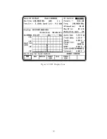
Page 85: ...39 Figure 3 12 RF Display Zone...
Page 88: ...Figure 3 14 Digital Voltmeter Screens 42...
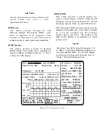
Page 102: ...Figure 3 22 Bar Graphs 56...
Page 107: ...Figure 3 24 Memory Screens 61...
Page 128: ...This Page Intentionally Left Blank 82...
Page 202: ...This Page Intentionally Left Blank 156...
Page 205: ...Figure 11 1 R 2670 with SECURENET Option Housing 159...
Page 206: ...This Page Intentionally Left Blank 160...
Page 218: ...Figure 13 8 Test Key Programming Display Figure 13 9 External Key Programming Display 172...
Page 225: ...Figure 13 12 Duplex Mode Display Zone 179...
Page 234: ...VOICE Figure 13 17 CLEAR SCOPE Markers 188...
Page 236: ...This Page Intentionally Left Blank 190...
Page 249: ...Figure 14 8 SECURENET CLEAR SCOPE Display of Output Modulation 203...
Page 252: ...This Page Intentionally Left Blank 206...
Page 256: ...210 This Page Intentionally Left Blank...
Page 267: ...Figure 17 7 Encryption Select Display Figure 17 7 Encryption Select Display 221 221...
Page 286: ...This Page Intentionally Left Blank 240...
Page 291: ...Figure 18 1 Radio BER Test Mode Audio Zone Figure 18 2 Radio BER Test Mode BER Meter 245...
Page 293: ...Figure 18 4 Receive BER 247...
Page 298: ...Figure 18 6 ASTRO CLEAR SCOPE Display of Output Modulation 252...
Page 304: ...Figure 21 1 PROJ 25 Version Screen Figure 21 2 PROJ 25 Options Screen 258...
Page 309: ...Figure 21 6 SET UP Display Screen Figure 21 7 Encryption Select Display 263...
Page 335: ...Figure 22 4 PROJ 25 CONV CLEAR SCOPE Display of Output Modulation 289...
Page 339: ...Figure 24 1 PROJ 25 Version Screen Figure 24 2 PROJ 25 Options Screen 293...
Page 354: ...Figure 25 3 Encryption Select Display Figure 25 4 Algorithm Select Display 308...
Page 369: ...B 6 This Page Intentionally Left Blank...
Page 379: ...This Page Intentionally Left Blank F 4...
Page 383: ...This Page Intentionally Left Blank H 2...
Page 389: ...J 4 This Page Intentionally Left Blank...
Page 393: ...This Page Intentionally Left Blank K 4...