


The BER metering screen will indicate the BER.
The digital bit pattern is also viewable on the
analyzer Ext Scope. Due to the features of digital
scopes, the generated eye pattern may be seen
more clearly by connecting the MOD OUT on the
analyzer front panel to a conventional
oscilloscope. The monitored eye pattern can be
seen at the DEMOD OUT port.
14-4.2 Radios With BER Test Capability and
Repeaters
Radios with BER capability and repeaters can be
tested by the analyzer using the V.52 BER test
pattern. In RF mode, the operation of both the radio
receiver and transmitter can be evaluated. To set up
the analyzer for the BER test, use the following
sequence:
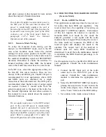
1. Connect the RF IN/OUT port of the
analyzer to the RF port of the radio under
test.
2. Place the cursor in the RF Zone and
configure the analyzer as shown below.
Set the monitor frequency of the analyzer
at the generate frequency of the radio to
be tested, and set the analyzer offset
frequency to correspond to that of the
radio.
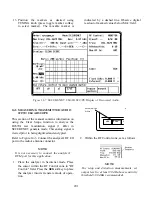
3. Set the controls in the Audio Zone as
follows:
Securenet 4.0
kHz
Code: BER
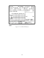
4. With the cursor on RF Display, press the
more softkey and select BER. The BER
metering will appear in the top left corner
of the screen.
5. Press the reset softkey to reset the BER
measurements.
The monitored or generated BIT pattern can be
observed by selecting MODULATION SCOPE in
the Display Zone.
Remote repeaters, modems or other devices using
a 600-ohm balance line can be tested by the
analyzer using baseband mode. To set up the
analyzer for baseband operation, refer to
paragraphs 14-10 and 14-11.
14.5 VOICE PATTERN TESTING IN
GENERATE MODE
This section contains the basic test setup for FM
receivers. Testing procedures are contained in
section 14 under the General Operations tab in
this manual.
The analyzer's DVM input is unbalanced (ground
referenced). Use an appropriate interface to
measure balanced circuits, such as certain
receiver audio outputs or telephone lines.
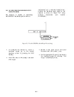
Refer to figure 14-3. Connect the analyzer's RF
I/O port to the radio antenna connector. Connect
the radio audio output to VERT/SINAD port of
the analyzer. Use
CAUTION
With some radios, grounding the speaker
leads will damage the audio circuitry. Use
isolation techniques on these radios.
197
Summary of Contents for R2600 Series
Page 8: ...3 7 1 3 AC DC Voltmeter 41 3 7 1 4 INT DIST EXT DIST Meter 43 v...
Page 46: ...This Page Intentionally Left Blank xxxvi...
Page 66: ...DISPLAY ZONE RF ZONE AUDIO ZONE Figure 3 1 Screen Zone Arrangement 20...
Page 68: ...Figure 3 2 System Help 22...
Page 83: ...Figure 3 11 General Sequence Mode Select 37...
Page 85: ...39 Figure 3 12 RF Display Zone...
Page 88: ...Figure 3 14 Digital Voltmeter Screens 42...
Page 102: ...Figure 3 22 Bar Graphs 56...
Page 107: ...Figure 3 24 Memory Screens 61...
Page 128: ...This Page Intentionally Left Blank 82...
Page 202: ...This Page Intentionally Left Blank 156...
Page 205: ...Figure 11 1 R 2670 with SECURENET Option Housing 159...
Page 206: ...This Page Intentionally Left Blank 160...
Page 218: ...Figure 13 8 Test Key Programming Display Figure 13 9 External Key Programming Display 172...
Page 225: ...Figure 13 12 Duplex Mode Display Zone 179...
Page 234: ...VOICE Figure 13 17 CLEAR SCOPE Markers 188...
Page 236: ...This Page Intentionally Left Blank 190...
Page 249: ...Figure 14 8 SECURENET CLEAR SCOPE Display of Output Modulation 203...
Page 252: ...This Page Intentionally Left Blank 206...
Page 256: ...210 This Page Intentionally Left Blank...
Page 267: ...Figure 17 7 Encryption Select Display Figure 17 7 Encryption Select Display 221 221...
Page 286: ...This Page Intentionally Left Blank 240...
Page 291: ...Figure 18 1 Radio BER Test Mode Audio Zone Figure 18 2 Radio BER Test Mode BER Meter 245...
Page 293: ...Figure 18 4 Receive BER 247...
Page 298: ...Figure 18 6 ASTRO CLEAR SCOPE Display of Output Modulation 252...
Page 304: ...Figure 21 1 PROJ 25 Version Screen Figure 21 2 PROJ 25 Options Screen 258...
Page 309: ...Figure 21 6 SET UP Display Screen Figure 21 7 Encryption Select Display 263...
Page 335: ...Figure 22 4 PROJ 25 CONV CLEAR SCOPE Display of Output Modulation 289...
Page 339: ...Figure 24 1 PROJ 25 Version Screen Figure 24 2 PROJ 25 Options Screen 293...
Page 354: ...Figure 25 3 Encryption Select Display Figure 25 4 Algorithm Select Display 308...
Page 369: ...B 6 This Page Intentionally Left Blank...
Page 379: ...This Page Intentionally Left Blank F 4...
Page 383: ...This Page Intentionally Left Blank H 2...
Page 389: ...J 4 This Page Intentionally Left Blank...
Page 393: ...This Page Intentionally Left Blank K 4...