


21-8 PROJ 25 CONV RF OPERATING
MODES
Select the RF operating mode by placing the
cursor in the "RF Control:" field in the RF Zone.
Use the desired softkey to select MONITOR or
GENERATE.
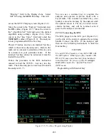
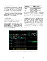
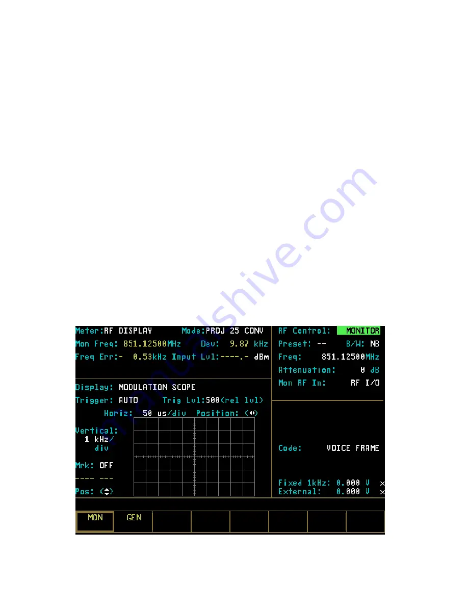
21-8.1 Monitor Mode
The Monitor mode (Figure 21-11) provides the
analyzer’s test receiver function which is used in
the testing of radio transmitters. In PROJ 25
CONV Monitor mode, the RF Zone is similar to
the RF Zone in standard mode. It is capable of
setting up the analyzer to monitor RF input
through its antenna or direct connection to the
transmitter.
The RF Zone in Monitor mode contains fields for
choosing the monitor bandwidth, frequency,
attenuation, and source of the Project 25 RF
signal.
The specific entry fields are as follows.
Preset
Refer to Section 21-8.5 Memory Screens
under the General Operation tab in this
manual for information on this field.
B/W
Selects either wide or narrow IF bandwidth of
the unit via softkey selection. Narrow
bandwidth is typically used for Project 25.
Freq
Enter the desired monitor frequency using
keypad or TUNING knob.
Attenuation
Selects the amount of attenuation at the RF
input to the monitor receiver using softkeys.
Selectable input attenuation is useful in
adjusting displays for a wide range of input
levels, as well as for use in high RF field
environments where intermodulation may cause
desensitization of the receiver.
Figure 21-11. Monitor Mode - RF Zone
267
Summary of Contents for R2600 Series
Page 8: ...3 7 1 3 AC DC Voltmeter 41 3 7 1 4 INT DIST EXT DIST Meter 43 v...
Page 46: ...This Page Intentionally Left Blank xxxvi...
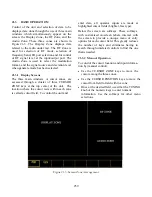
Page 66: ...DISPLAY ZONE RF ZONE AUDIO ZONE Figure 3 1 Screen Zone Arrangement 20...
Page 68: ...Figure 3 2 System Help 22...
Page 83: ...Figure 3 11 General Sequence Mode Select 37...
Page 85: ...39 Figure 3 12 RF Display Zone...
Page 88: ...Figure 3 14 Digital Voltmeter Screens 42...
Page 102: ...Figure 3 22 Bar Graphs 56...
Page 107: ...Figure 3 24 Memory Screens 61...
Page 128: ...This Page Intentionally Left Blank 82...
Page 202: ...This Page Intentionally Left Blank 156...
Page 205: ...Figure 11 1 R 2670 with SECURENET Option Housing 159...
Page 206: ...This Page Intentionally Left Blank 160...
Page 218: ...Figure 13 8 Test Key Programming Display Figure 13 9 External Key Programming Display 172...
Page 225: ...Figure 13 12 Duplex Mode Display Zone 179...
Page 234: ...VOICE Figure 13 17 CLEAR SCOPE Markers 188...
Page 236: ...This Page Intentionally Left Blank 190...
Page 249: ...Figure 14 8 SECURENET CLEAR SCOPE Display of Output Modulation 203...
Page 252: ...This Page Intentionally Left Blank 206...
Page 256: ...210 This Page Intentionally Left Blank...
Page 267: ...Figure 17 7 Encryption Select Display Figure 17 7 Encryption Select Display 221 221...
Page 286: ...This Page Intentionally Left Blank 240...
Page 291: ...Figure 18 1 Radio BER Test Mode Audio Zone Figure 18 2 Radio BER Test Mode BER Meter 245...
Page 293: ...Figure 18 4 Receive BER 247...
Page 298: ...Figure 18 6 ASTRO CLEAR SCOPE Display of Output Modulation 252...
Page 304: ...Figure 21 1 PROJ 25 Version Screen Figure 21 2 PROJ 25 Options Screen 258...
Page 309: ...Figure 21 6 SET UP Display Screen Figure 21 7 Encryption Select Display 263...
Page 335: ...Figure 22 4 PROJ 25 CONV CLEAR SCOPE Display of Output Modulation 289...
Page 339: ...Figure 24 1 PROJ 25 Version Screen Figure 24 2 PROJ 25 Options Screen 293...
Page 354: ...Figure 25 3 Encryption Select Display Figure 25 4 Algorithm Select Display 308...
Page 369: ...B 6 This Page Intentionally Left Blank...
Page 379: ...This Page Intentionally Left Blank F 4...
Page 383: ...This Page Intentionally Left Blank H 2...
Page 389: ...J 4 This Page Intentionally Left Blank...
Page 393: ...This Page Intentionally Left Blank K 4...