


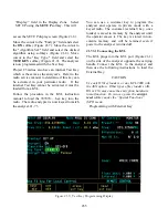


21-3.3 Expanded Display
Some fields have the ability to expand their
contents to fill the entire screen. These fields
consist of the following:
Spectrum analyzer, clear scope, mod scope, ext
scope, bar graph displays
Encode tables
Dedicated keys
21-3.4 Dedicated Keys
Refer to Section 2-2.1 in this manual for an
explanation of the HELP, MEM, SPF, and CAL
keys.
21-3.5 Remote Operation
The R2670 Communications System Analyzer is
equipped with a standard RS-232 interface. This
interface may be used to remotely control the
analyzer using a set of commands, queries, and
responses that are defined in the General
Dynamics R2600 Series Communications System
Analyzer Programming Reference Manual (68-
80309E55).
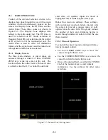
21-3.6 HELP
The analyzer provides on-screen operating
instructions via the dedicated HELP key. Help
screens are organized such that each display area
has an associated help screen pertaining to that
area of the screen. System help is available via a
softkey within each help screen. Use the
return
softkey to return to the function in progress.
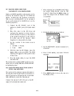
21-4 ENCRYPTION
CAPABILITIES
When in PROJ 25 CONV mode, the R2670 can
operate in clear or hardware encrypted modes.
Project 25 equipment converts normal speech
patterns to their digital equivalent and then uses
an encryption algorithm to encrypt data for
transmission. A receiving radio, using the same
algorithm and a matching key, automatically
reverses the process so you can hear a normal
audio message.
A set of either U.S. or International encryption
algorithms is available with the Project 25.
Algorithms include Data-Encryption System
(DES) - a U.S. Federal Government encryption
standard, and Digital Voice Protection (DVP) - a
Motorola Proprietary encryption algorithm, and
DVI - a Motorola Proprietary encryption
algorithm for international use. Within a set, each
algorithm is individually selectable:
Domestic: DES-OFB, DES-XL, DVP-XL
International: DVI-XL, DVP-XL
21-5
TEST SETUP
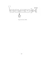
Connecting a Radio
Use a 50 ohm BNC cable and an N to BNC
adapter to connect from the RF I/O port of the
R2670 analyzer to the antenna port of the radio as
shown in Figure 21-4.
CAUTION
When in Monitor mode, adjust the squelch to
where the LED indicator for squelch just
turns off or is closed. When the signal from
the radio is present, the squelch LED will
illuminate indicating that squelch has been
detected and there is a signal present.
CAUTION
Observe the input power ratings and warnings
of the analyzer to insure that no damage
occurs to the analyzer.
260
Summary of Contents for R2600 Series
Page 8: ...3 7 1 3 AC DC Voltmeter 41 3 7 1 4 INT DIST EXT DIST Meter 43 v...
Page 46: ...This Page Intentionally Left Blank xxxvi...
Page 66: ...DISPLAY ZONE RF ZONE AUDIO ZONE Figure 3 1 Screen Zone Arrangement 20...
Page 68: ...Figure 3 2 System Help 22...
Page 83: ...Figure 3 11 General Sequence Mode Select 37...
Page 85: ...39 Figure 3 12 RF Display Zone...
Page 88: ...Figure 3 14 Digital Voltmeter Screens 42...
Page 102: ...Figure 3 22 Bar Graphs 56...
Page 107: ...Figure 3 24 Memory Screens 61...
Page 128: ...This Page Intentionally Left Blank 82...
Page 202: ...This Page Intentionally Left Blank 156...
Page 205: ...Figure 11 1 R 2670 with SECURENET Option Housing 159...
Page 206: ...This Page Intentionally Left Blank 160...
Page 218: ...Figure 13 8 Test Key Programming Display Figure 13 9 External Key Programming Display 172...
Page 225: ...Figure 13 12 Duplex Mode Display Zone 179...
Page 234: ...VOICE Figure 13 17 CLEAR SCOPE Markers 188...
Page 236: ...This Page Intentionally Left Blank 190...
Page 249: ...Figure 14 8 SECURENET CLEAR SCOPE Display of Output Modulation 203...
Page 252: ...This Page Intentionally Left Blank 206...
Page 256: ...210 This Page Intentionally Left Blank...
Page 267: ...Figure 17 7 Encryption Select Display Figure 17 7 Encryption Select Display 221 221...
Page 286: ...This Page Intentionally Left Blank 240...
Page 291: ...Figure 18 1 Radio BER Test Mode Audio Zone Figure 18 2 Radio BER Test Mode BER Meter 245...
Page 293: ...Figure 18 4 Receive BER 247...
Page 298: ...Figure 18 6 ASTRO CLEAR SCOPE Display of Output Modulation 252...
Page 304: ...Figure 21 1 PROJ 25 Version Screen Figure 21 2 PROJ 25 Options Screen 258...
Page 309: ...Figure 21 6 SET UP Display Screen Figure 21 7 Encryption Select Display 263...
Page 335: ...Figure 22 4 PROJ 25 CONV CLEAR SCOPE Display of Output Modulation 289...
Page 339: ...Figure 24 1 PROJ 25 Version Screen Figure 24 2 PROJ 25 Options Screen 293...
Page 354: ...Figure 25 3 Encryption Select Display Figure 25 4 Algorithm Select Display 308...
Page 369: ...B 6 This Page Intentionally Left Blank...
Page 379: ...This Page Intentionally Left Blank F 4...
Page 383: ...This Page Intentionally Left Blank H 2...
Page 389: ...J 4 This Page Intentionally Left Blank...
Page 393: ...This Page Intentionally Left Blank K 4...