


100
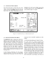
6-7 SYSTEM INITIATED TRUNKING
The
SYSTEM INIT
softkey in the "Meter:" field con-
figures the analyzer to display the current data and
test status for the system initiated trunked test
sequence. The analyzer simulates the central con-
troller (the "system") calling the radio under test.
In the following subsections, the call sequence
selected in Dispatch. For details on testing System
Initiated Phone Interconnect, Call Alert, and
Failsoft call sequences, refer to Section III,
Applications, in this manual.
NOTE
Fleet, Subfleet, and Unit ID information must
be entered before the execution of a System
Initiated test. If a Radio Initiated test is
executed prior to the System Initiated test,
these fields are automatically updated. If
required, refer to 6-8.1 for information
related to entry and storage of system/fleet
map configurations.
When the test is started, the analyzer generates an
idle OSW pattern on the control channel selected
for a short period of time so the radio can acquire
the control channel. After the time has elapsed, the
analyzer directs the radio to the voice channel and
provides the voice channel handshake signaling
required by the type of Trunk Signaling used.
Throughout the signaling process the status
thermometer is updated at the appropriate time.
6-7.1 System Initiated Dispatch Trunk I
Signaling
The radio receives the control channel message to
move to a voice channel and switches to that
channel. When the radio detects the high-speed data
word and low-speed data word, the radio unmutes
and stays on the voice channel until the test is
terminated.
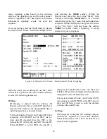
To set up testing, select the Trunk mode by placing
the cursor in the "Mode:" field in the Display Zone,
and selecting the
TRUNK
softkey. Place the cursor
in the "Meter:" field and press the softkey
SYSTEM
INIT
to view current data and test status for a system
initiated trunked test sequence. Within the Display
zone, place the cursor in the "Sig Type:" field and
press the softkey
TRUNK I
to select Trunk I
signaling. A screen similar to figure 6-7 appears.
Parameter selection is similar to Radio Init
Dispatch Trunk I described in paragraph 6-6.1.
Summary of Contents for R2600 Series
Page 8: ...3 7 1 3 AC DC Voltmeter 41 3 7 1 4 INT DIST EXT DIST Meter 43 v...
Page 46: ...This Page Intentionally Left Blank xxxvi...
Page 66: ...DISPLAY ZONE RF ZONE AUDIO ZONE Figure 3 1 Screen Zone Arrangement 20...
Page 68: ...Figure 3 2 System Help 22...
Page 83: ...Figure 3 11 General Sequence Mode Select 37...
Page 85: ...39 Figure 3 12 RF Display Zone...
Page 88: ...Figure 3 14 Digital Voltmeter Screens 42...
Page 102: ...Figure 3 22 Bar Graphs 56...
Page 107: ...Figure 3 24 Memory Screens 61...
Page 128: ...This Page Intentionally Left Blank 82...
Page 202: ...This Page Intentionally Left Blank 156...
Page 205: ...Figure 11 1 R 2670 with SECURENET Option Housing 159...
Page 206: ...This Page Intentionally Left Blank 160...
Page 218: ...Figure 13 8 Test Key Programming Display Figure 13 9 External Key Programming Display 172...
Page 225: ...Figure 13 12 Duplex Mode Display Zone 179...
Page 234: ...VOICE Figure 13 17 CLEAR SCOPE Markers 188...
Page 236: ...This Page Intentionally Left Blank 190...
Page 249: ...Figure 14 8 SECURENET CLEAR SCOPE Display of Output Modulation 203...
Page 252: ...This Page Intentionally Left Blank 206...
Page 256: ...210 This Page Intentionally Left Blank...
Page 267: ...Figure 17 7 Encryption Select Display Figure 17 7 Encryption Select Display 221 221...
Page 286: ...This Page Intentionally Left Blank 240...
Page 291: ...Figure 18 1 Radio BER Test Mode Audio Zone Figure 18 2 Radio BER Test Mode BER Meter 245...
Page 293: ...Figure 18 4 Receive BER 247...
Page 298: ...Figure 18 6 ASTRO CLEAR SCOPE Display of Output Modulation 252...
Page 304: ...Figure 21 1 PROJ 25 Version Screen Figure 21 2 PROJ 25 Options Screen 258...
Page 309: ...Figure 21 6 SET UP Display Screen Figure 21 7 Encryption Select Display 263...
Page 335: ...Figure 22 4 PROJ 25 CONV CLEAR SCOPE Display of Output Modulation 289...
Page 339: ...Figure 24 1 PROJ 25 Version Screen Figure 24 2 PROJ 25 Options Screen 293...
Page 354: ...Figure 25 3 Encryption Select Display Figure 25 4 Algorithm Select Display 308...
Page 369: ...B 6 This Page Intentionally Left Blank...
Page 379: ...This Page Intentionally Left Blank F 4...
Page 383: ...This Page Intentionally Left Blank H 2...
Page 389: ...J 4 This Page Intentionally Left Blank...
Page 393: ...This Page Intentionally Left Blank K 4...