


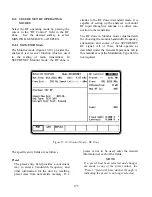


13-7.1.3 Encrypt Self Test
A self test of the encryption functions is
performed at power up. The "Encrypt Self Test:"
field in the SET UP display (figure 13-6)
indicates the results of the self test, passed or
failed.
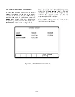
13-7.2 Programming with Test Key
Connect the proper key loading cable between
the Key Variable Loader port of the analyzer
(figure 11-1) and the programming port on the
radio (refer to radio operator's manual).
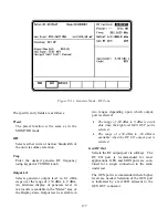
To program the radio with a test key, place the
cursor in "Display:" field in the Display Zone.
Select SET UP using the
SET UP
softkey. This
accesses the SET UP display screen (figure 13-6).
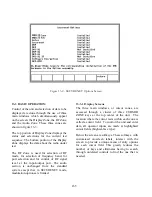
Move cursor to "Algorithm Sel:" field and select
desired algorithm using softkeys (figure 13-7).
Move cursor to "Key Type:" field.
Apply power to the radio if not already on.
Select
key load radio
softkey. This will exercise
the Key Variable Loader feature of the R2670
and start an automatic transfer of the test key
from the analyzer to the radio. The R2670 will
display "Radio key load complete."
To verify that a key has been loaded into the
radio, disconnect the key loading cable, turn the
radio off then back on. If the key load was
unsuccessful, the radio will display key fail if it
has a visual readout or will make an audio sound
to indicate key fail.
CAUTION
Disconnect the key loading cable before
continuing. Testing the radio with the key
loading cable still connected could result in
loss of the key.
To test the radio with the analyzer, be sure TEST
KEY is displayed in the "Key Type:" field. This
completes test key loading. It is all right to exit
the SET UP screen.
13-7.3 Programming with External Key
You can use a customer key to program the
analyzer and operate in private mode with a
keyed radio. The customer (external) key, once
loaded, is saved in memory by the analyzer until
the operator erases it. The key is stored in non-
volatile memory and will be retained even if
power to the analyzer is turned off.
13-7.3.1 Connecting the Key Inserter
The key inserter plugs into the Key Variable
Loader (KVL) port (figure 11-1) on the side of
the analyzer opposite the carrying handle.
Connect the key inserter to the analyzer and then
use the following instructions to load the external
key.
CAUTION
Use only DX, or any KVL 3000 with the ASN
option, key loaders. Other types of key
loaders (AX, BX or CX) may cause the
encryption hardware to malfunction. To
recover, press the encrypt reset softkey under
the “Special Functions” (SPF) menu.
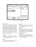
13-7.3.2 Loading External Key
To initiate loading an external key, place cursor
in "Display:" field in the Display Zone and select
SET UP mode display using the
SET UP
softkey.
Move cursor to "Algorithm Sel:" field and select
desired algorithm using softkeys (figure 13-7).
Move cursor to "Key Type:" field.
Press the
load ext key
softkey to initiate the key
load sequence.
Push the switch on the key inserter to begin
loading. This activates the programming
function. When programming is complete, the
key inserter displays "pass" if the key load
procedure was successful. The analyzer displays
a message Ext key passed." If the key load
173
Summary of Contents for R2600 Series
Page 8: ...3 7 1 3 AC DC Voltmeter 41 3 7 1 4 INT DIST EXT DIST Meter 43 v...
Page 46: ...This Page Intentionally Left Blank xxxvi...
Page 66: ...DISPLAY ZONE RF ZONE AUDIO ZONE Figure 3 1 Screen Zone Arrangement 20...
Page 68: ...Figure 3 2 System Help 22...
Page 83: ...Figure 3 11 General Sequence Mode Select 37...
Page 85: ...39 Figure 3 12 RF Display Zone...
Page 88: ...Figure 3 14 Digital Voltmeter Screens 42...
Page 102: ...Figure 3 22 Bar Graphs 56...
Page 107: ...Figure 3 24 Memory Screens 61...
Page 128: ...This Page Intentionally Left Blank 82...
Page 202: ...This Page Intentionally Left Blank 156...
Page 205: ...Figure 11 1 R 2670 with SECURENET Option Housing 159...
Page 206: ...This Page Intentionally Left Blank 160...
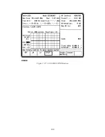
Page 218: ...Figure 13 8 Test Key Programming Display Figure 13 9 External Key Programming Display 172...
Page 225: ...Figure 13 12 Duplex Mode Display Zone 179...
Page 234: ...VOICE Figure 13 17 CLEAR SCOPE Markers 188...
Page 236: ...This Page Intentionally Left Blank 190...
Page 249: ...Figure 14 8 SECURENET CLEAR SCOPE Display of Output Modulation 203...
Page 252: ...This Page Intentionally Left Blank 206...
Page 256: ...210 This Page Intentionally Left Blank...
Page 267: ...Figure 17 7 Encryption Select Display Figure 17 7 Encryption Select Display 221 221...
Page 286: ...This Page Intentionally Left Blank 240...
Page 291: ...Figure 18 1 Radio BER Test Mode Audio Zone Figure 18 2 Radio BER Test Mode BER Meter 245...
Page 293: ...Figure 18 4 Receive BER 247...
Page 298: ...Figure 18 6 ASTRO CLEAR SCOPE Display of Output Modulation 252...
Page 304: ...Figure 21 1 PROJ 25 Version Screen Figure 21 2 PROJ 25 Options Screen 258...
Page 309: ...Figure 21 6 SET UP Display Screen Figure 21 7 Encryption Select Display 263...
Page 335: ...Figure 22 4 PROJ 25 CONV CLEAR SCOPE Display of Output Modulation 289...
Page 339: ...Figure 24 1 PROJ 25 Version Screen Figure 24 2 PROJ 25 Options Screen 293...
Page 354: ...Figure 25 3 Encryption Select Display Figure 25 4 Algorithm Select Display 308...
Page 369: ...B 6 This Page Intentionally Left Blank...
Page 379: ...This Page Intentionally Left Blank F 4...
Page 383: ...This Page Intentionally Left Blank H 2...
Page 389: ...J 4 This Page Intentionally Left Blank...
Page 393: ...This Page Intentionally Left Blank K 4...