


The specific entry fields are as follows:
Preset
The preset function is the same as in the
Monitor mode.
B/W
Selects either wide or narrow bandwidth of
the unit via softkey selection.
Freq
Enter the desired generate RF frequency
using keypad or TUNING knob.
Output Lvl
Selects generator output level in 0.1 dBm
steps over the range of -130 dBm to 0 dBm.
An alternate display of generate level in
microvolts is available in the "Meter:" area of
the Display Zone. Output level is available in
two ranges depending upon which output
port is selected:
The range of -80 dBm to 0 dBm is available
when the high level GEN OUT port is selected.
The range of -130 dBm to -50 dBm is avail-
able when the RF I/O output port is selected.
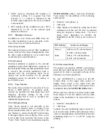
Gen RF Out
Selects the RF output port via softkeys. The
RF I/O port is recommended for most
applications. GEN and MON ports are com-
bined for a single connection to the radio
under test. The GEN port is recommended
where higher levels are needed. Selection of
the GEN port is indicated by a red LED
adjacent to the GEN OUT connector.
CAUTION
Do not apply input power to the GEN OUT
port. In the event RF power is inadvertently
applied, the port is protected by an in-line
RF fuse. This fuse may be accessed by
unscrewing the front of the BNC connector
out of the front panel.
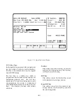
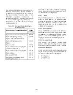
17-8.3 DUPLEX
Mode
The Duplex Mode (figure 17-13) provides a
simultaneous RF generator BER pattern output
that is offset in frequency from the monitor
center frequency and fully adjustable in output
level.
This capability provides for servicing full
duplex radio equipment as well as repeaters and
radios operating with offset transmit and
receive frequencies. The Display zone provides
softkey selections for generated or monitored
clear baseband signal as shown in figure 3-12.
Specific controls which further configure the
Duplex mode are located within the RF Control
Zone when DUPLEX is first selected.
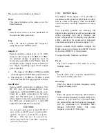
The specific entry fields are as follows:
Preset
The preset function is the same as in the
Monitor mode.
B/W
Selects either wide or narrow bandwidth of
the unit via softkey selection.
Mon Freq
Enter the desired monitor frequency using
keypad or tuning knob.
Offset
Enter the generator frequency offset relative
to the monitor frequency entered. Offset fre-
quencies of –999.99975 to +999.99975 MHz
are allowed, but the final generate frequency
will be constrained to 000.40000 MHz
through 999.99995 MHz. The offset
frequency is set in 2.5 kHz steps.
228
Summary of Contents for R2600 Series
Page 8: ...3 7 1 3 AC DC Voltmeter 41 3 7 1 4 INT DIST EXT DIST Meter 43 v...
Page 46: ...This Page Intentionally Left Blank xxxvi...
Page 66: ...DISPLAY ZONE RF ZONE AUDIO ZONE Figure 3 1 Screen Zone Arrangement 20...
Page 68: ...Figure 3 2 System Help 22...
Page 83: ...Figure 3 11 General Sequence Mode Select 37...
Page 85: ...39 Figure 3 12 RF Display Zone...
Page 88: ...Figure 3 14 Digital Voltmeter Screens 42...
Page 102: ...Figure 3 22 Bar Graphs 56...
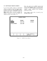
Page 107: ...Figure 3 24 Memory Screens 61...
Page 128: ...This Page Intentionally Left Blank 82...
Page 202: ...This Page Intentionally Left Blank 156...
Page 205: ...Figure 11 1 R 2670 with SECURENET Option Housing 159...
Page 206: ...This Page Intentionally Left Blank 160...
Page 218: ...Figure 13 8 Test Key Programming Display Figure 13 9 External Key Programming Display 172...
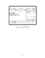
Page 225: ...Figure 13 12 Duplex Mode Display Zone 179...
Page 234: ...VOICE Figure 13 17 CLEAR SCOPE Markers 188...
Page 236: ...This Page Intentionally Left Blank 190...
Page 249: ...Figure 14 8 SECURENET CLEAR SCOPE Display of Output Modulation 203...
Page 252: ...This Page Intentionally Left Blank 206...
Page 256: ...210 This Page Intentionally Left Blank...
Page 267: ...Figure 17 7 Encryption Select Display Figure 17 7 Encryption Select Display 221 221...
Page 286: ...This Page Intentionally Left Blank 240...
Page 291: ...Figure 18 1 Radio BER Test Mode Audio Zone Figure 18 2 Radio BER Test Mode BER Meter 245...
Page 293: ...Figure 18 4 Receive BER 247...
Page 298: ...Figure 18 6 ASTRO CLEAR SCOPE Display of Output Modulation 252...
Page 304: ...Figure 21 1 PROJ 25 Version Screen Figure 21 2 PROJ 25 Options Screen 258...
Page 309: ...Figure 21 6 SET UP Display Screen Figure 21 7 Encryption Select Display 263...
Page 335: ...Figure 22 4 PROJ 25 CONV CLEAR SCOPE Display of Output Modulation 289...
Page 339: ...Figure 24 1 PROJ 25 Version Screen Figure 24 2 PROJ 25 Options Screen 293...
Page 354: ...Figure 25 3 Encryption Select Display Figure 25 4 Algorithm Select Display 308...
Page 369: ...B 6 This Page Intentionally Left Blank...
Page 379: ...This Page Intentionally Left Blank F 4...
Page 383: ...This Page Intentionally Left Blank H 2...
Page 389: ...J 4 This Page Intentionally Left Blank...
Page 393: ...This Page Intentionally Left Blank K 4...