


95
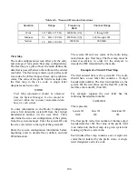
Table 6-4. Available Transmit Frequency Ranges and Channel Plans (900 MHz Selection)
Frequency
Range
(MHz)
Channel Range
Channel Spacing
(kHz)
Xmit/Rcv Offset
(MHz)
900 MHz
935.01250 -
940.98750
000 - 479
12.5
+39
VHF/UHF
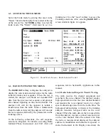
Selection of the VHF/UHF band configures the
trunking analyzer for the VHF or UHF frequency
band. The operator enters the frequency and
channel configuration of the radio to be tested
from the Trunk II Radio Configuration screen.
The VHF/UHF band does not have a constant
offset between the transmit and receive pairs as
found in other trunking bands. The operator must
enter the Transmit and Receive frequencies for
both the control channel and the voice channel.
CCTx:
CCTx is the control channel transmit frequency
of the analyzer. The control channel frequency
can be changed by moving the cursor into the
CCTx cursor field and changing the value with
the keypad or with the tuning knob. When the
control channel frequency is changed, the corre-
sponding channel number is also updated. If the
frequency selected is out of range of the
frequency channel plan, the corresponding
channel number is dashed out.
As a convenience, the control channel can also be
entered by moving the cursor to the associated
channel position on the display and selecting a
channel number with the keypad or tuning knob.
When the channel number is changed, the
corresponding frequency value is changed. If the
channel number selected is out of range of the
frequency channel plan, the corresponding
frequency is dashed out.
Splinter channels can only be entered by
frequency. Standard channels can be entered by
frequency or channel number (channel numbers
only map to standard channel frequencies).
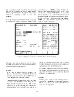
CCRx:
The cursor position for CCRx appears only when
the band selection is VHF/UHF. CCRx sets the
analyzer control channel frequency to receive
control channel signaling from the radio. The
control channel frequency can be changed by
moving the cursor into the CCRx cursor field and
changing the value with the keypad or with the
tuning knob. When the control channel frequency
is changed, the corresponding channel number
also is updated. If the frequency selected is out of
range of the frequency channel plan, the
corresponding channel number is dashed out.
The control channel can also be changed by
moving the cursor to the associated channel
position on the display and selecting a channel
number by the keypad or tuning knob. When the
channel number is changed, the corresponding
frequency value is changed. If the channel
number selected is out of range of the frequency
channel plan, the corresponding frequency is
dashed out.
VCTx:
VCTx sets the voice channel transmit frequency
of the analyzer. The voice channel frequency can
be changed by moving the cursor into the VCTx
cursor field and changing the value with the
keypad or with the tuning knob. When the voice
channel frequency is changed, the corresponding
channel number is also updated. If the channel
number selected is out of range of the frequency
channel plan, the corresponding frequency is
dashed out.
As a convenience, the voice channel can also be
entered by moving the cursor to the associated
Summary of Contents for R2600 Series
Page 8: ...3 7 1 3 AC DC Voltmeter 41 3 7 1 4 INT DIST EXT DIST Meter 43 v...
Page 46: ...This Page Intentionally Left Blank xxxvi...
Page 66: ...DISPLAY ZONE RF ZONE AUDIO ZONE Figure 3 1 Screen Zone Arrangement 20...
Page 68: ...Figure 3 2 System Help 22...
Page 83: ...Figure 3 11 General Sequence Mode Select 37...
Page 85: ...39 Figure 3 12 RF Display Zone...
Page 88: ...Figure 3 14 Digital Voltmeter Screens 42...
Page 102: ...Figure 3 22 Bar Graphs 56...
Page 107: ...Figure 3 24 Memory Screens 61...
Page 128: ...This Page Intentionally Left Blank 82...
Page 202: ...This Page Intentionally Left Blank 156...
Page 205: ...Figure 11 1 R 2670 with SECURENET Option Housing 159...
Page 206: ...This Page Intentionally Left Blank 160...
Page 218: ...Figure 13 8 Test Key Programming Display Figure 13 9 External Key Programming Display 172...
Page 225: ...Figure 13 12 Duplex Mode Display Zone 179...
Page 234: ...VOICE Figure 13 17 CLEAR SCOPE Markers 188...
Page 236: ...This Page Intentionally Left Blank 190...
Page 249: ...Figure 14 8 SECURENET CLEAR SCOPE Display of Output Modulation 203...
Page 252: ...This Page Intentionally Left Blank 206...
Page 256: ...210 This Page Intentionally Left Blank...
Page 267: ...Figure 17 7 Encryption Select Display Figure 17 7 Encryption Select Display 221 221...
Page 286: ...This Page Intentionally Left Blank 240...
Page 291: ...Figure 18 1 Radio BER Test Mode Audio Zone Figure 18 2 Radio BER Test Mode BER Meter 245...
Page 293: ...Figure 18 4 Receive BER 247...
Page 298: ...Figure 18 6 ASTRO CLEAR SCOPE Display of Output Modulation 252...
Page 304: ...Figure 21 1 PROJ 25 Version Screen Figure 21 2 PROJ 25 Options Screen 258...
Page 309: ...Figure 21 6 SET UP Display Screen Figure 21 7 Encryption Select Display 263...
Page 335: ...Figure 22 4 PROJ 25 CONV CLEAR SCOPE Display of Output Modulation 289...
Page 339: ...Figure 24 1 PROJ 25 Version Screen Figure 24 2 PROJ 25 Options Screen 293...
Page 354: ...Figure 25 3 Encryption Select Display Figure 25 4 Algorithm Select Display 308...
Page 369: ...B 6 This Page Intentionally Left Blank...
Page 379: ...This Page Intentionally Left Blank F 4...
Page 383: ...This Page Intentionally Left Blank H 2...
Page 389: ...J 4 This Page Intentionally Left Blank...
Page 393: ...This Page Intentionally Left Blank K 4...