


It provides an RF frequency counter function
where the monitor scans over a selected fre-
quency range and locks on to the carrier that is
applied to its input. The direct frequency is then
displayed, eliminating the need to first enter the
carrier frequency and read its error. The acquired
signal is measured to a frequency resolution of
1 Hz.
The RF signal input, either from the ANT or from
the RF I/O port, may be displayed. The analyzer
scans a specified frequency range to automa-
tically acquire and tune to an input signal from 20
MHz to 999.9999 MHz.
Tuning typically occurs within 5 seconds. For
faster acquisition, limit the scan range to
100 MHz increments. This is done by setting the
High and Low range limits to narrow the scan
range. Move the cursor to the desired Hi or Lo
range field in the Meter portion of the screen.
Select the range desired either by using the
numeric keypad or the optical TUNING knob.
NOTE
The range of values for the low range setting
is from 0 to 9 (x 100 MHz). The range of val-
ues for the high range setting can be from 0 to
10 (x 100 MHz), with the 10 implying
maximum frequency range, or 999.9999 MHz.
Minimum input signal level for automatic fre-
quency acquisition is -30 dBm at the antenna port
and +20 dBm at the transceiver port. When the
input signal is removed, the scanning operation
will resume.
When scanning, the "Freq:" field within the RF
Control zone indicates
scanning
.
When a carrier
is acquired, this changes to
metering
. The actual
measured frequency is displayed in the Meter
zone along with modulation and level data as des-
cribed above for RF Display.
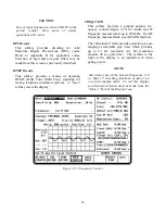
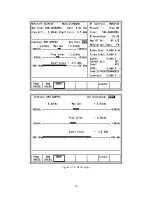
3-7.1.3 AC/DC Voltmeter
The analyzer provides a general purpose AC/DC
digital voltmeter (figure 3-14). The voltmeter
input is the same front panel BNC port that also
serves as the input for the SINAD/DIST meter,
the VERT oscilloscope input, and the frequency
COUNTER IN.
Move the cursor to the "Range:" field. Select
either auto-ranging or a specific voltage range
(AUTO, 1V, 10V, or 100V DC) by pressing the
applicable softkey. Maximum AC range is
70 VAC. If the optional battery pack is installed,
an additional selection is available to read the
battery voltage.
CAUTION
The maximum analyzer input voltage is 42.4
volts peak AC or 60 volts DC.
The data portion of this screen will show a hori-
zontally oriented bar graph for an analog indica-
tion along with a digital readout of the measured
voltage (up to 4 digits resolution).
In the AC mode, the measured input is also
displayed in dBm, referenced to 1mW into
600 ohms.
NOTE
Optional "C" message or CCITT filters, along
with a 600 ohm load, are available for
selection at the ACVM, SINAD, and Dis-
tortion meter inputs. If your unit is equipped
with one of these, they are selectable through
the Special Function screen (refer to section
3-8.5). If one of these is selected an
appropriate message will appear on the
message line just above the softkey labels.
CAUTION: Selection of either filters or load
can affect readings within these meter
functions.
41
Summary of Contents for R2600 Series
Page 8: ...3 7 1 3 AC DC Voltmeter 41 3 7 1 4 INT DIST EXT DIST Meter 43 v...
Page 46: ...This Page Intentionally Left Blank xxxvi...
Page 66: ...DISPLAY ZONE RF ZONE AUDIO ZONE Figure 3 1 Screen Zone Arrangement 20...
Page 68: ...Figure 3 2 System Help 22...
Page 83: ...Figure 3 11 General Sequence Mode Select 37...
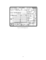
Page 85: ...39 Figure 3 12 RF Display Zone...
Page 88: ...Figure 3 14 Digital Voltmeter Screens 42...
Page 102: ...Figure 3 22 Bar Graphs 56...
Page 107: ...Figure 3 24 Memory Screens 61...
Page 128: ...This Page Intentionally Left Blank 82...
Page 202: ...This Page Intentionally Left Blank 156...
Page 205: ...Figure 11 1 R 2670 with SECURENET Option Housing 159...
Page 206: ...This Page Intentionally Left Blank 160...
Page 218: ...Figure 13 8 Test Key Programming Display Figure 13 9 External Key Programming Display 172...
Page 225: ...Figure 13 12 Duplex Mode Display Zone 179...
Page 234: ...VOICE Figure 13 17 CLEAR SCOPE Markers 188...
Page 236: ...This Page Intentionally Left Blank 190...
Page 249: ...Figure 14 8 SECURENET CLEAR SCOPE Display of Output Modulation 203...
Page 252: ...This Page Intentionally Left Blank 206...
Page 256: ...210 This Page Intentionally Left Blank...
Page 267: ...Figure 17 7 Encryption Select Display Figure 17 7 Encryption Select Display 221 221...
Page 286: ...This Page Intentionally Left Blank 240...
Page 291: ...Figure 18 1 Radio BER Test Mode Audio Zone Figure 18 2 Radio BER Test Mode BER Meter 245...
Page 293: ...Figure 18 4 Receive BER 247...
Page 298: ...Figure 18 6 ASTRO CLEAR SCOPE Display of Output Modulation 252...
Page 304: ...Figure 21 1 PROJ 25 Version Screen Figure 21 2 PROJ 25 Options Screen 258...
Page 309: ...Figure 21 6 SET UP Display Screen Figure 21 7 Encryption Select Display 263...
Page 335: ...Figure 22 4 PROJ 25 CONV CLEAR SCOPE Display of Output Modulation 289...
Page 339: ...Figure 24 1 PROJ 25 Version Screen Figure 24 2 PROJ 25 Options Screen 293...
Page 354: ...Figure 25 3 Encryption Select Display Figure 25 4 Algorithm Select Display 308...
Page 369: ...B 6 This Page Intentionally Left Blank...
Page 379: ...This Page Intentionally Left Blank F 4...
Page 383: ...This Page Intentionally Left Blank H 2...
Page 389: ...J 4 This Page Intentionally Left Blank...
Page 393: ...This Page Intentionally Left Blank K 4...