


First
try
encrypt reset
, and if that
fails, notify the Service
Representative.
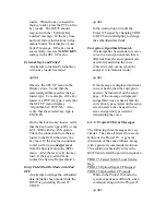
No Response From Option
The R2670 has attempted to
communicate with the Project 25
Option but has not received a
response.
qwdId:
Verify that the Project 25 Option is
installed. This can be done by
inspecting the Installed Options
window from the Special Functions
(SPF)
page.
If the option is installed, press the
encrypt reset
softkey from the
system functions line on the SPF
window. This will reset the R2670.
Retry the test. If the message is
redisplayed,
perform
the
nvm clear
from the SPF menu. (This function
will clear all settings previously
input.) Retry the test. If the message
is redisplayed, contact the Service
Representative.
Option Not Responding To Calibration
Msg
A command to start the modulation
calibration for the Project 25 Option
has been generated but the option is
not
responding.
qwdId:
Perform
an
nvm clear
from the
Special Functions (SPF) menu to
restart calibration. If the option fails
to respond, notify the Service
Representative.
Astro Option-Failed DSP SRAM Test
Indicates failure of the DSP powerup
test of the three DSP static RAM
chips on the option card.
Astro Option-Failed DSP ROM Test
Indicates failure of the DSP powerup
test of the DSP program ROM on the
option
card.
Astro Option-Failed DSP Startup
Indicates failure of the DSP powerup
sequence has been detected by the
HC11 when the required DSP startup
message is not correctly received
from the DSP.
ASTRO Option Timed Out
Indicates failure of the option has
been detected by the 68k during
powerup when the required
diagnostic response has not been
received from the HC11.
qwdId:
For the above four messages, first try
to reset the analyzer. If this fails
notify the Service Representative.
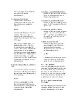
L-2 WARNINGS
Project 25 Warnings also fall into two
categories: Informational Warnings and
User Prompt Warnings. Informational
Warnings provide feedback to the user,
informing the user of results of actions.
User Prompt Warnings prompt the user
to perform some action to continue.
L-2.1 Project
25
Informational
Warnings
The following Project 25 Informational
Messages occur as the result of some
user or system action. All of these
Summary of Contents for R2600 Series
Page 8: ...3 7 1 3 AC DC Voltmeter 41 3 7 1 4 INT DIST EXT DIST Meter 43 v...
Page 46: ...This Page Intentionally Left Blank xxxvi...
Page 66: ...DISPLAY ZONE RF ZONE AUDIO ZONE Figure 3 1 Screen Zone Arrangement 20...
Page 68: ...Figure 3 2 System Help 22...
Page 83: ...Figure 3 11 General Sequence Mode Select 37...
Page 85: ...39 Figure 3 12 RF Display Zone...
Page 88: ...Figure 3 14 Digital Voltmeter Screens 42...
Page 102: ...Figure 3 22 Bar Graphs 56...
Page 107: ...Figure 3 24 Memory Screens 61...
Page 128: ...This Page Intentionally Left Blank 82...
Page 202: ...This Page Intentionally Left Blank 156...
Page 205: ...Figure 11 1 R 2670 with SECURENET Option Housing 159...
Page 206: ...This Page Intentionally Left Blank 160...
Page 218: ...Figure 13 8 Test Key Programming Display Figure 13 9 External Key Programming Display 172...
Page 225: ...Figure 13 12 Duplex Mode Display Zone 179...
Page 234: ...VOICE Figure 13 17 CLEAR SCOPE Markers 188...
Page 236: ...This Page Intentionally Left Blank 190...
Page 249: ...Figure 14 8 SECURENET CLEAR SCOPE Display of Output Modulation 203...
Page 252: ...This Page Intentionally Left Blank 206...
Page 256: ...210 This Page Intentionally Left Blank...
Page 267: ...Figure 17 7 Encryption Select Display Figure 17 7 Encryption Select Display 221 221...
Page 286: ...This Page Intentionally Left Blank 240...
Page 291: ...Figure 18 1 Radio BER Test Mode Audio Zone Figure 18 2 Radio BER Test Mode BER Meter 245...
Page 293: ...Figure 18 4 Receive BER 247...
Page 298: ...Figure 18 6 ASTRO CLEAR SCOPE Display of Output Modulation 252...
Page 304: ...Figure 21 1 PROJ 25 Version Screen Figure 21 2 PROJ 25 Options Screen 258...
Page 309: ...Figure 21 6 SET UP Display Screen Figure 21 7 Encryption Select Display 263...
Page 335: ...Figure 22 4 PROJ 25 CONV CLEAR SCOPE Display of Output Modulation 289...
Page 339: ...Figure 24 1 PROJ 25 Version Screen Figure 24 2 PROJ 25 Options Screen 293...
Page 354: ...Figure 25 3 Encryption Select Display Figure 25 4 Algorithm Select Display 308...
Page 369: ...B 6 This Page Intentionally Left Blank...
Page 379: ...This Page Intentionally Left Blank F 4...
Page 383: ...This Page Intentionally Left Blank H 2...
Page 389: ...J 4 This Page Intentionally Left Blank...
Page 393: ...This Page Intentionally Left Blank K 4...