


Section 11
SECURENET OPTION INTRODUCTION
11-1 INTRODUCTION
This manual contains information for using the
R2670 FDMA Digital Communications System
Analyzer with SECURENET Options. The
SECURENET Option provides unique testing
features for communications equipment using
SECURENET encoding and modulation
principles. Standard R2670 capabilities are
retained. The additional SECURENET test
sequences are accessed via the LCD display,
screen-defined softkeys, numeric keypad, cursor
movement keys, and optical tuning knob. The
SECURENET Option functions may also be
accessed via the remote control interface port.
11-2 CAPABILITIES
The SECURENET Option gives the R2670 the
capability of monitoring and generating
SECURENET signals. A SECURENET signal
relates to a Motorola proprietary signaling
scheme in which a 12 kbps serial bit stream is
mapped into one of two corresponding
amplitudes, filtered digitally, and then modulated
onto an RF carrier. Most of the SECURENET
user interface operates exactly like that of the
standard R2670. Several new features were
added to test the unique requirements of user
SECURENET equipment.
Voice Mode System Testing
Voice mode provides SECURENET-
compatible modulation and demodulation with
vocoding. The SECURENET Option generate
and monitor modes support actual functional
voice testing in encrypted mode using either a
test key or an operating key loaded from a
separate compatible keyloader.
Bit Error Rate (BER) Testing
A BER test pattern can be selected to modulate
the R2670 generator section. A BER test
pattern can likewise be decoded by the R2670
in monitor mode. BER tests can also be
conducted in duplex mode for loop testing.
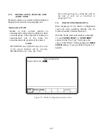
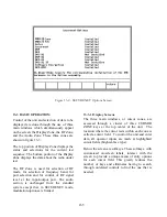
Dedicated Test Screens
Dedicated test screens can be setup as a start-up
default condition or as a programmable test set-
up. Dedicated SECURENET test screens are
zoned with RF and Audio Modulation control
screens to simultaneously display test results
along with their test conditions.
Baseband Audio Scope Display
The display provides a graphic image of the
audio baseband signal. This baseband signal is
selectable at either the vocoder input in
generate mode or the vocoder output in monitor
mode.
157
Summary of Contents for R2600 Series
Page 8: ...3 7 1 3 AC DC Voltmeter 41 3 7 1 4 INT DIST EXT DIST Meter 43 v...
Page 46: ...This Page Intentionally Left Blank xxxvi...
Page 66: ...DISPLAY ZONE RF ZONE AUDIO ZONE Figure 3 1 Screen Zone Arrangement 20...
Page 68: ...Figure 3 2 System Help 22...
Page 83: ...Figure 3 11 General Sequence Mode Select 37...
Page 85: ...39 Figure 3 12 RF Display Zone...
Page 88: ...Figure 3 14 Digital Voltmeter Screens 42...
Page 102: ...Figure 3 22 Bar Graphs 56...
Page 107: ...Figure 3 24 Memory Screens 61...
Page 128: ...This Page Intentionally Left Blank 82...
Page 202: ...This Page Intentionally Left Blank 156...
Page 205: ...Figure 11 1 R 2670 with SECURENET Option Housing 159...
Page 206: ...This Page Intentionally Left Blank 160...
Page 218: ...Figure 13 8 Test Key Programming Display Figure 13 9 External Key Programming Display 172...
Page 225: ...Figure 13 12 Duplex Mode Display Zone 179...
Page 234: ...VOICE Figure 13 17 CLEAR SCOPE Markers 188...
Page 236: ...This Page Intentionally Left Blank 190...
Page 249: ...Figure 14 8 SECURENET CLEAR SCOPE Display of Output Modulation 203...
Page 252: ...This Page Intentionally Left Blank 206...
Page 256: ...210 This Page Intentionally Left Blank...
Page 267: ...Figure 17 7 Encryption Select Display Figure 17 7 Encryption Select Display 221 221...
Page 286: ...This Page Intentionally Left Blank 240...
Page 291: ...Figure 18 1 Radio BER Test Mode Audio Zone Figure 18 2 Radio BER Test Mode BER Meter 245...
Page 293: ...Figure 18 4 Receive BER 247...
Page 298: ...Figure 18 6 ASTRO CLEAR SCOPE Display of Output Modulation 252...
Page 304: ...Figure 21 1 PROJ 25 Version Screen Figure 21 2 PROJ 25 Options Screen 258...
Page 309: ...Figure 21 6 SET UP Display Screen Figure 21 7 Encryption Select Display 263...
Page 335: ...Figure 22 4 PROJ 25 CONV CLEAR SCOPE Display of Output Modulation 289...
Page 339: ...Figure 24 1 PROJ 25 Version Screen Figure 24 2 PROJ 25 Options Screen 293...
Page 354: ...Figure 25 3 Encryption Select Display Figure 25 4 Algorithm Select Display 308...
Page 369: ...B 6 This Page Intentionally Left Blank...
Page 379: ...This Page Intentionally Left Blank F 4...
Page 383: ...This Page Intentionally Left Blank H 2...
Page 389: ...J 4 This Page Intentionally Left Blank...
Page 393: ...This Page Intentionally Left Blank K 4...