


11-3 SECURENET OPTION HOUSING
11-3.1 Description
The SECURENET Option housing (figure 11-1)
is an external module containing circuitry and
connectors to support SECURENET functions.
The SECURENET Option housing attaches to
the rear of the R2670 analyzer. In some
instances, the Option housing may be attached
along with another option housing or in
conjunction with the R2670 battery pack
(optional). The battery pack, if used, mounts on
the back of the final option housing.
11-3.2 Connectors
The SECURENET Option housing has two
connectors as shown in figure 11-1. Both
connectors are located on the side of the housing.
The KVL connector provides a receptacle for
loading an external encryption key or for
programming a radio with a test key. The other
connector is an interface port.
Key Variable Loader (Kvl) Port
The KVL port allows the analyzer to be
preloaded with a user-selected encryption key
from any compatible keyloader (key inserter).
The port also is used with an optional cable to
transfer test keys from the analyzer to a radio
being tested. The R2670 with SECURENET
Option is compatible with the following
Motorola key inserters: T3010DX, T3011DX,
T3012DX, T3013DX, T3014DX, or any KVL
3000 with the ASN option.
Serial Port (25 Pin)
The serial interface port is multiplexed to
provide the future addition of an HDLC
wireline serial data interface or an RS-232
interface for data communications.
158
Summary of Contents for R2600 Series
Page 8: ...3 7 1 3 AC DC Voltmeter 41 3 7 1 4 INT DIST EXT DIST Meter 43 v...
Page 46: ...This Page Intentionally Left Blank xxxvi...
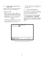
Page 66: ...DISPLAY ZONE RF ZONE AUDIO ZONE Figure 3 1 Screen Zone Arrangement 20...
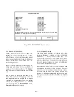
Page 68: ...Figure 3 2 System Help 22...
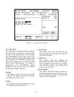
Page 83: ...Figure 3 11 General Sequence Mode Select 37...
Page 85: ...39 Figure 3 12 RF Display Zone...
Page 88: ...Figure 3 14 Digital Voltmeter Screens 42...
Page 102: ...Figure 3 22 Bar Graphs 56...
Page 107: ...Figure 3 24 Memory Screens 61...
Page 128: ...This Page Intentionally Left Blank 82...
Page 202: ...This Page Intentionally Left Blank 156...
Page 205: ...Figure 11 1 R 2670 with SECURENET Option Housing 159...
Page 206: ...This Page Intentionally Left Blank 160...
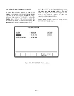
Page 218: ...Figure 13 8 Test Key Programming Display Figure 13 9 External Key Programming Display 172...
Page 225: ...Figure 13 12 Duplex Mode Display Zone 179...
Page 234: ...VOICE Figure 13 17 CLEAR SCOPE Markers 188...
Page 236: ...This Page Intentionally Left Blank 190...
Page 249: ...Figure 14 8 SECURENET CLEAR SCOPE Display of Output Modulation 203...
Page 252: ...This Page Intentionally Left Blank 206...
Page 256: ...210 This Page Intentionally Left Blank...
Page 267: ...Figure 17 7 Encryption Select Display Figure 17 7 Encryption Select Display 221 221...
Page 286: ...This Page Intentionally Left Blank 240...
Page 291: ...Figure 18 1 Radio BER Test Mode Audio Zone Figure 18 2 Radio BER Test Mode BER Meter 245...
Page 293: ...Figure 18 4 Receive BER 247...
Page 298: ...Figure 18 6 ASTRO CLEAR SCOPE Display of Output Modulation 252...
Page 304: ...Figure 21 1 PROJ 25 Version Screen Figure 21 2 PROJ 25 Options Screen 258...
Page 309: ...Figure 21 6 SET UP Display Screen Figure 21 7 Encryption Select Display 263...
Page 335: ...Figure 22 4 PROJ 25 CONV CLEAR SCOPE Display of Output Modulation 289...
Page 339: ...Figure 24 1 PROJ 25 Version Screen Figure 24 2 PROJ 25 Options Screen 293...
Page 354: ...Figure 25 3 Encryption Select Display Figure 25 4 Algorithm Select Display 308...
Page 369: ...B 6 This Page Intentionally Left Blank...
Page 379: ...This Page Intentionally Left Blank F 4...
Page 383: ...This Page Intentionally Left Blank H 2...
Page 389: ...J 4 This Page Intentionally Left Blank...
Page 393: ...This Page Intentionally Left Blank K 4...