


Section 10
ASTRO TRUNKING APPLICATIONS
10-1
BASIC TRUNKED RADIO TESTING
This section of the manual contains information
on typical test setups to perform some of the more
common trunked radio tests using the R2670
Digital Communications System Analyzer with
Trunking Option.
The
start test
softkey initiates the test sequence
defined by the parameters selected on the
trunking screen. If the parameters selected are not
valid, the test sequence is terminated and an error
message is displayed. If the parameters selected
are valid when the
start test
softkey is pressed,
the
start test
softkey is replaced with the
stop test
softkey. For a list of error and warning messages,
refer to Appendix G.
10-2 DISPATCH
TESTING
10-2.1 Radio Initiated Dispatch Test, Astro
Signaling
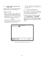
Configure the analyzer for trunk mode (paragraph
9-5) and Radio Initiated Testing (paragraph 9-6).
NOTE
SMARTZONE configures the analyzer to
perform a SMARTZONE affiliation
sequence prior to executing the dispatch test
sequence. If the radio is not capable of
SMARTZONE auto affiliation, the selection
should be set to DISABLED.
1. Enter the following parameters:
Sig Type:
ASTRO VSELP or
ASTRO IMBE
ID Disp:
HEX or DEC
Call Seq:
DISPATCH
2. Set the System ID.
3. Enter the CCTx or Control Channel number.
Enter the VCTx or voice channel number.
NOTE
Splinter channels can only be entered by
frequency. Standard channels can be
entered by frequency or channel number
(channel numbers only map to standard
channel frequencies).
147
Summary of Contents for R2600 Series
Page 8: ...3 7 1 3 AC DC Voltmeter 41 3 7 1 4 INT DIST EXT DIST Meter 43 v...
Page 46: ...This Page Intentionally Left Blank xxxvi...
Page 66: ...DISPLAY ZONE RF ZONE AUDIO ZONE Figure 3 1 Screen Zone Arrangement 20...
Page 68: ...Figure 3 2 System Help 22...
Page 83: ...Figure 3 11 General Sequence Mode Select 37...
Page 85: ...39 Figure 3 12 RF Display Zone...
Page 88: ...Figure 3 14 Digital Voltmeter Screens 42...
Page 102: ...Figure 3 22 Bar Graphs 56...
Page 107: ...Figure 3 24 Memory Screens 61...
Page 128: ...This Page Intentionally Left Blank 82...
Page 202: ...This Page Intentionally Left Blank 156...
Page 205: ...Figure 11 1 R 2670 with SECURENET Option Housing 159...
Page 206: ...This Page Intentionally Left Blank 160...
Page 218: ...Figure 13 8 Test Key Programming Display Figure 13 9 External Key Programming Display 172...
Page 225: ...Figure 13 12 Duplex Mode Display Zone 179...
Page 234: ...VOICE Figure 13 17 CLEAR SCOPE Markers 188...
Page 236: ...This Page Intentionally Left Blank 190...
Page 249: ...Figure 14 8 SECURENET CLEAR SCOPE Display of Output Modulation 203...
Page 252: ...This Page Intentionally Left Blank 206...
Page 256: ...210 This Page Intentionally Left Blank...
Page 267: ...Figure 17 7 Encryption Select Display Figure 17 7 Encryption Select Display 221 221...
Page 286: ...This Page Intentionally Left Blank 240...
Page 291: ...Figure 18 1 Radio BER Test Mode Audio Zone Figure 18 2 Radio BER Test Mode BER Meter 245...
Page 293: ...Figure 18 4 Receive BER 247...
Page 298: ...Figure 18 6 ASTRO CLEAR SCOPE Display of Output Modulation 252...
Page 304: ...Figure 21 1 PROJ 25 Version Screen Figure 21 2 PROJ 25 Options Screen 258...
Page 309: ...Figure 21 6 SET UP Display Screen Figure 21 7 Encryption Select Display 263...
Page 335: ...Figure 22 4 PROJ 25 CONV CLEAR SCOPE Display of Output Modulation 289...
Page 339: ...Figure 24 1 PROJ 25 Version Screen Figure 24 2 PROJ 25 Options Screen 293...
Page 354: ...Figure 25 3 Encryption Select Display Figure 25 4 Algorithm Select Display 308...
Page 369: ...B 6 This Page Intentionally Left Blank...
Page 379: ...This Page Intentionally Left Blank F 4...
Page 383: ...This Page Intentionally Left Blank H 2...
Page 389: ...J 4 This Page Intentionally Left Blank...
Page 393: ...This Page Intentionally Left Blank K 4...