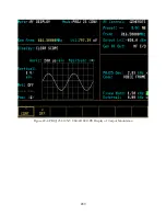


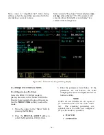


24-4.5 PROJ 25 Trunking BER Screen
Upon selection of the PROJ 25 Trunking
BER (Bit Error Rate) test the screen zones
defined in section 24-3 will display
parameters associated with Project 25
Trunking BER testing. The BER test
performs a monitor operation where the
analyzer will receive either C4FM or LSM
V.52 test pattern. The results of the BER are
displayed in the Display Zone. Refer to
paragraph 24-4.5.1 Display Zone.
The Display Zone consists of a single section
with several fields that relate to BER testing.
A description of each field is included
below.
Meter
The meter provides the standard PROJ 25
Trunking meter selections and a reset
softkey. This softkey allows the user to clear
the accumulated BER values and restart the
BER computation.
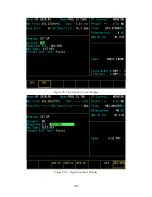
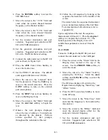
24-4.5.1 RF Zone
The BASE test will configure the RF zone
for monitor operation. The fields available
will be similar to the RF Zone fields when in
standard mode. A description of the RF zone
fields is as follows:
RF Control
This provides MONITOR as the only
selection. MONITOR is required when in
BER test mode.
Preset
This field allows the user to select
predefined memory presets. This is the same
function that is available when in standard
mode (refer to GENERAL OPERATIONS).
B/W
This is the bandwidth selection field and has
the same functionality as the B/W in standard
mode (refer to GENERAL OPERATIONS).
The user can select either NB (Narrow Band)
or WB (Wide Band). The NB should be used
for BASE testing only.
Mon Freq
This field allows the user to specify the
frequency that the analyzer will receive the
V.52 test pattern from the base station being
tested. This is the frequency that the base
station being tested is transmitting.
Mon
Allows the user to select the amount of
attenuation to apply to the received RF signal.
This can be 0, 20, or 40 dB. It also allows the
selection of the receive port, either ANT or RF
I/O.
24-4.5.2 Audio Zone
The audio zone allows the user to enter
parameters relating to the received signal. A
description of the audio zone fields is as
follows:
Code
This defines the test pattern to be received.
The only option available is V.52 BER.
303
Summary of Contents for R2600 Series
Page 8: ...3 7 1 3 AC DC Voltmeter 41 3 7 1 4 INT DIST EXT DIST Meter 43 v...
Page 46: ...This Page Intentionally Left Blank xxxvi...
Page 66: ...DISPLAY ZONE RF ZONE AUDIO ZONE Figure 3 1 Screen Zone Arrangement 20...
Page 68: ...Figure 3 2 System Help 22...
Page 83: ...Figure 3 11 General Sequence Mode Select 37...
Page 85: ...39 Figure 3 12 RF Display Zone...
Page 88: ...Figure 3 14 Digital Voltmeter Screens 42...
Page 102: ...Figure 3 22 Bar Graphs 56...
Page 107: ...Figure 3 24 Memory Screens 61...
Page 128: ...This Page Intentionally Left Blank 82...
Page 202: ...This Page Intentionally Left Blank 156...
Page 205: ...Figure 11 1 R 2670 with SECURENET Option Housing 159...
Page 206: ...This Page Intentionally Left Blank 160...
Page 218: ...Figure 13 8 Test Key Programming Display Figure 13 9 External Key Programming Display 172...
Page 225: ...Figure 13 12 Duplex Mode Display Zone 179...
Page 234: ...VOICE Figure 13 17 CLEAR SCOPE Markers 188...
Page 236: ...This Page Intentionally Left Blank 190...
Page 249: ...Figure 14 8 SECURENET CLEAR SCOPE Display of Output Modulation 203...
Page 252: ...This Page Intentionally Left Blank 206...
Page 256: ...210 This Page Intentionally Left Blank...
Page 267: ...Figure 17 7 Encryption Select Display Figure 17 7 Encryption Select Display 221 221...
Page 286: ...This Page Intentionally Left Blank 240...
Page 291: ...Figure 18 1 Radio BER Test Mode Audio Zone Figure 18 2 Radio BER Test Mode BER Meter 245...
Page 293: ...Figure 18 4 Receive BER 247...
Page 298: ...Figure 18 6 ASTRO CLEAR SCOPE Display of Output Modulation 252...
Page 304: ...Figure 21 1 PROJ 25 Version Screen Figure 21 2 PROJ 25 Options Screen 258...
Page 309: ...Figure 21 6 SET UP Display Screen Figure 21 7 Encryption Select Display 263...
Page 335: ...Figure 22 4 PROJ 25 CONV CLEAR SCOPE Display of Output Modulation 289...
Page 339: ...Figure 24 1 PROJ 25 Version Screen Figure 24 2 PROJ 25 Options Screen 293...
Page 354: ...Figure 25 3 Encryption Select Display Figure 25 4 Algorithm Select Display 308...
Page 369: ...B 6 This Page Intentionally Left Blank...
Page 379: ...This Page Intentionally Left Blank F 4...
Page 383: ...This Page Intentionally Left Blank H 2...
Page 389: ...J 4 This Page Intentionally Left Blank...
Page 393: ...This Page Intentionally Left Blank K 4...