


by moving it within the RF memory table to a
location just above or below the preset numbers
being scanned.
It is recommended that frequencies in the RF
memory table be grouped according to their
modulation type and bandwidth because these
parameters must be manually changed in the
analyzer's RF Control zone. If an AM frequency
(e.g. aircraft band) is intermixed with FM
frequencies (e.g. public service band) in the scan
list and the analyzer is set to FM mode, radio
traffic on the AM frequency will cause the
scanner to lock, but the received audio will be
unintelligible and the modulation measurement
meaningless.
Because breaking the receiver squelch causes the
analyzer to stop scanning, it is important to
properly adjust the squelch control. If the
squelch is adjusted too loosely (counterclockwise
rotation of the squelch knob), it is possible that
desired signals will not be strong enough to break
the squelch and the analyzer will not stop and
dwell on the channel. To adjust the squelch
control for proper scanning operation, turn the
squelch control fully counterclockwise and
activate the Preset Scan mode. The analyzer will
not scan because it will lock on the first
frequency due to the squelch being open. Now
slowly rotate the squelch control clockwise, just
until the squelch light goes out, the noise in the
speaker stops and the unit begins to scan. If an
actual signal is received while the squelch is
being adjusted, wait until it ends before resuming
the adjustment. For maximum sensitivity, the
squelch level should be adjusted as loose as
possible (counterclockwise) without being broken
by receiver noise.
To halt the scanning operation at any time, press
the
RF DISPLAY
softkey. This stops the scanning
process and leaves the analyzer locked onto the last
scanned frequency prior to the key press.
NOTE
When the unit is in the Preset Scan mode, the
response time to key presses will be somewhat
slower than normal. For best results, it is
recommended that you do not leave Preset
Scan active when it is not being used.
48
Summary of Contents for R2600 Series
Page 8: ...3 7 1 3 AC DC Voltmeter 41 3 7 1 4 INT DIST EXT DIST Meter 43 v...
Page 46: ...This Page Intentionally Left Blank xxxvi...
Page 66: ...DISPLAY ZONE RF ZONE AUDIO ZONE Figure 3 1 Screen Zone Arrangement 20...
Page 68: ...Figure 3 2 System Help 22...
Page 83: ...Figure 3 11 General Sequence Mode Select 37...
Page 85: ...39 Figure 3 12 RF Display Zone...
Page 88: ...Figure 3 14 Digital Voltmeter Screens 42...
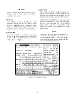
Page 102: ...Figure 3 22 Bar Graphs 56...
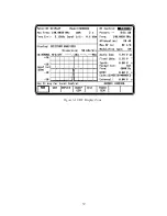
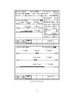
Page 107: ...Figure 3 24 Memory Screens 61...
Page 128: ...This Page Intentionally Left Blank 82...
Page 202: ...This Page Intentionally Left Blank 156...
Page 205: ...Figure 11 1 R 2670 with SECURENET Option Housing 159...
Page 206: ...This Page Intentionally Left Blank 160...
Page 218: ...Figure 13 8 Test Key Programming Display Figure 13 9 External Key Programming Display 172...
Page 225: ...Figure 13 12 Duplex Mode Display Zone 179...
Page 234: ...VOICE Figure 13 17 CLEAR SCOPE Markers 188...
Page 236: ...This Page Intentionally Left Blank 190...
Page 249: ...Figure 14 8 SECURENET CLEAR SCOPE Display of Output Modulation 203...
Page 252: ...This Page Intentionally Left Blank 206...
Page 256: ...210 This Page Intentionally Left Blank...
Page 267: ...Figure 17 7 Encryption Select Display Figure 17 7 Encryption Select Display 221 221...
Page 286: ...This Page Intentionally Left Blank 240...
Page 291: ...Figure 18 1 Radio BER Test Mode Audio Zone Figure 18 2 Radio BER Test Mode BER Meter 245...
Page 293: ...Figure 18 4 Receive BER 247...
Page 298: ...Figure 18 6 ASTRO CLEAR SCOPE Display of Output Modulation 252...
Page 304: ...Figure 21 1 PROJ 25 Version Screen Figure 21 2 PROJ 25 Options Screen 258...
Page 309: ...Figure 21 6 SET UP Display Screen Figure 21 7 Encryption Select Display 263...
Page 335: ...Figure 22 4 PROJ 25 CONV CLEAR SCOPE Display of Output Modulation 289...
Page 339: ...Figure 24 1 PROJ 25 Version Screen Figure 24 2 PROJ 25 Options Screen 293...
Page 354: ...Figure 25 3 Encryption Select Display Figure 25 4 Algorithm Select Display 308...
Page 369: ...B 6 This Page Intentionally Left Blank...
Page 379: ...This Page Intentionally Left Blank F 4...
Page 383: ...This Page Intentionally Left Blank H 2...
Page 389: ...J 4 This Page Intentionally Left Blank...
Page 393: ...This Page Intentionally Left Blank K 4...