


Mon
Gen
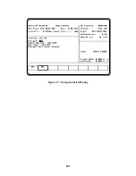
This field actually contains two separate
fields, one for monitor input attenuation and
one for monitor port selection. Refer to the
Monitor mode description for further details.
This field actually contains two separate fields,
one for generate output level and one for gener-
ate output port selection. Refer to the Generate
mode description for further details.
Figure 17-13. Duplex Mode - Display Zone
17-9 ASTRO AUDIO/MODULATION
CONTROL
The Audio Zone located at the lower right of the
screen (figure 17-14) is used to control the
multi-purpose audio synthesizer section of the
unit. Signals generated by the audio synthesizer
are coupled internally to the generator
modulation input as well as to the MOD OUT
connector on front panel. The main categories of
modulation in ASTRO mode are Voice Frame
and Bit Error Rate (BER). Many of the features
available in standard mode are not available in
ASTRO mode. The Audio Zone has been
changed accordingly to simplify testing of
ASTRO radios and equipment.
Each modulation signal has a cursor field for
entering its desired level. Use the keypad or
TUNING knob to enter the desired level.
An additional cursor field, adjacent to each level
entry, is used to switch each selection on and off
using softkeys. This field is located at the
extreme right side of the zone. There are two
possible conditions for this softkey selection.
229
Summary of Contents for R2600 Series
Page 8: ...3 7 1 3 AC DC Voltmeter 41 3 7 1 4 INT DIST EXT DIST Meter 43 v...
Page 46: ...This Page Intentionally Left Blank xxxvi...
Page 66: ...DISPLAY ZONE RF ZONE AUDIO ZONE Figure 3 1 Screen Zone Arrangement 20...
Page 68: ...Figure 3 2 System Help 22...
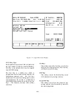
Page 83: ...Figure 3 11 General Sequence Mode Select 37...
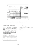
Page 85: ...39 Figure 3 12 RF Display Zone...
Page 88: ...Figure 3 14 Digital Voltmeter Screens 42...
Page 102: ...Figure 3 22 Bar Graphs 56...
Page 107: ...Figure 3 24 Memory Screens 61...
Page 128: ...This Page Intentionally Left Blank 82...
Page 202: ...This Page Intentionally Left Blank 156...
Page 205: ...Figure 11 1 R 2670 with SECURENET Option Housing 159...
Page 206: ...This Page Intentionally Left Blank 160...
Page 218: ...Figure 13 8 Test Key Programming Display Figure 13 9 External Key Programming Display 172...
Page 225: ...Figure 13 12 Duplex Mode Display Zone 179...
Page 234: ...VOICE Figure 13 17 CLEAR SCOPE Markers 188...
Page 236: ...This Page Intentionally Left Blank 190...
Page 249: ...Figure 14 8 SECURENET CLEAR SCOPE Display of Output Modulation 203...
Page 252: ...This Page Intentionally Left Blank 206...
Page 256: ...210 This Page Intentionally Left Blank...
Page 267: ...Figure 17 7 Encryption Select Display Figure 17 7 Encryption Select Display 221 221...
Page 286: ...This Page Intentionally Left Blank 240...
Page 291: ...Figure 18 1 Radio BER Test Mode Audio Zone Figure 18 2 Radio BER Test Mode BER Meter 245...
Page 293: ...Figure 18 4 Receive BER 247...
Page 298: ...Figure 18 6 ASTRO CLEAR SCOPE Display of Output Modulation 252...
Page 304: ...Figure 21 1 PROJ 25 Version Screen Figure 21 2 PROJ 25 Options Screen 258...
Page 309: ...Figure 21 6 SET UP Display Screen Figure 21 7 Encryption Select Display 263...
Page 335: ...Figure 22 4 PROJ 25 CONV CLEAR SCOPE Display of Output Modulation 289...
Page 339: ...Figure 24 1 PROJ 25 Version Screen Figure 24 2 PROJ 25 Options Screen 293...
Page 354: ...Figure 25 3 Encryption Select Display Figure 25 4 Algorithm Select Display 308...
Page 369: ...B 6 This Page Intentionally Left Blank...
Page 379: ...This Page Intentionally Left Blank F 4...
Page 383: ...This Page Intentionally Left Blank H 2...
Page 389: ...J 4 This Page Intentionally Left Blank...
Page 393: ...This Page Intentionally Left Blank K 4...