


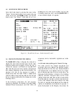


Parameter selection is similar to Radio Initiated
Dispatch Trunk I described in paragraph 6-6.1, with
the addition of the following parameter:
Auto Aff
The Auto Aff: selection on the analyzer con-
figures the analyzer to respond to the
SMARTZONE registration sequence. The Auto
Aff: selection is only available when Trunk II
signaling has been selected. The operator has the
option of disabling the auto affiliation sequence,
or selecting the SMARTZONE affiliation
sequence. If the radio is not capable of
SMARTZONE auto affiliation, the selection
should be set to DISABLED. If auto affiliation is
disabled, the analyzer transmits idle data on the
control channel until the radio initiates the test
sequence.
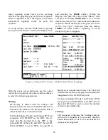
6-6.5 Radio Initiated Dispatch Trunk II
Testing Testing the Auto Affiliation
Feature
After setting up the test conditions, with the radio
turned "off", press the start test softkey to activate
control channel signaling. Turn the radio "on" when
the prompt message appears so it can lock to the
control channel and register. Successful registration
will be indicated by seeing the squelch indicator
LED flash briefly followed by the presence of
decoded radio ID parameters. The call type M1
should be displayed to indicate that an auto
affiliation sequence has been received. At this time,
the radio may be keyed to proceed with the radio
initiated calling sequence. The radio will remain
registered as long as it remains powered up and
there have been no changes in basic test
configuration. Stopping and re-starting the test
requires re-registration as long as SMARTZONE is
selected at the "Auto Aff:" field on the screen.
NOTE
If changes to the test setup entries are made
after a test has been started, even though
theses changes appear on the screen, they will
not be entered as part of the test until the test
is ended and restarted. Similarly, if invalid
entries are made for frequency or other
parameters, they may be accepted until a final
validity check is done by the system at the time
the "start test" softkey is pressed.
99
Summary of Contents for R2600 Series
Page 8: ...3 7 1 3 AC DC Voltmeter 41 3 7 1 4 INT DIST EXT DIST Meter 43 v...
Page 46: ...This Page Intentionally Left Blank xxxvi...
Page 66: ...DISPLAY ZONE RF ZONE AUDIO ZONE Figure 3 1 Screen Zone Arrangement 20...
Page 68: ...Figure 3 2 System Help 22...
Page 83: ...Figure 3 11 General Sequence Mode Select 37...
Page 85: ...39 Figure 3 12 RF Display Zone...
Page 88: ...Figure 3 14 Digital Voltmeter Screens 42...
Page 102: ...Figure 3 22 Bar Graphs 56...
Page 107: ...Figure 3 24 Memory Screens 61...
Page 128: ...This Page Intentionally Left Blank 82...
Page 202: ...This Page Intentionally Left Blank 156...
Page 205: ...Figure 11 1 R 2670 with SECURENET Option Housing 159...
Page 206: ...This Page Intentionally Left Blank 160...
Page 218: ...Figure 13 8 Test Key Programming Display Figure 13 9 External Key Programming Display 172...
Page 225: ...Figure 13 12 Duplex Mode Display Zone 179...
Page 234: ...VOICE Figure 13 17 CLEAR SCOPE Markers 188...
Page 236: ...This Page Intentionally Left Blank 190...
Page 249: ...Figure 14 8 SECURENET CLEAR SCOPE Display of Output Modulation 203...
Page 252: ...This Page Intentionally Left Blank 206...
Page 256: ...210 This Page Intentionally Left Blank...
Page 267: ...Figure 17 7 Encryption Select Display Figure 17 7 Encryption Select Display 221 221...
Page 286: ...This Page Intentionally Left Blank 240...
Page 291: ...Figure 18 1 Radio BER Test Mode Audio Zone Figure 18 2 Radio BER Test Mode BER Meter 245...
Page 293: ...Figure 18 4 Receive BER 247...
Page 298: ...Figure 18 6 ASTRO CLEAR SCOPE Display of Output Modulation 252...
Page 304: ...Figure 21 1 PROJ 25 Version Screen Figure 21 2 PROJ 25 Options Screen 258...
Page 309: ...Figure 21 6 SET UP Display Screen Figure 21 7 Encryption Select Display 263...
Page 335: ...Figure 22 4 PROJ 25 CONV CLEAR SCOPE Display of Output Modulation 289...
Page 339: ...Figure 24 1 PROJ 25 Version Screen Figure 24 2 PROJ 25 Options Screen 293...
Page 354: ...Figure 25 3 Encryption Select Display Figure 25 4 Algorithm Select Display 308...
Page 369: ...B 6 This Page Intentionally Left Blank...
Page 379: ...This Page Intentionally Left Blank F 4...
Page 383: ...This Page Intentionally Left Blank H 2...
Page 389: ...J 4 This Page Intentionally Left Blank...
Page 393: ...This Page Intentionally Left Blank K 4...