


Section 14
SECURENET OPTION APPLICATIONS
CAUTION
When testing a radio, observe the following precautions:
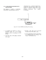
Do not use an antenna on the analyzer for over-the-air testing.
Use double-shielded cables on the analyzer to carry signals to and from the radio.
Locate the analyzer at least 35 feet from the antenna of a unit that is working in the same
system that the analyzer is testing.
Adjust the squelch to where the led indicator for squelch just turns off or is closed. When the
signal from the radio is present, the squelch LED will illuminate indicating that squelch has
been detected and there is a signal present.
14.1 Basic SECURENET Radio Testing
This section of the manual contains information on
how to connect equipment under test to the R2670
Analyzer. It is a supplement to sections 13 and 14
under the General Operations tab of this manual.
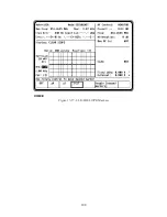
14-1.1
Setting the Deviation Level
The deviation of the radio can be set with greater
accuracy by configuring the R2670 Analyzer in the
following manner:
Display Zone
Mode: SECURENET
Display: BAR GRAPHS
RF ZONE
RF Control: MONITOR
B/W: WB
Both the digital display and the bar graph results
are improved by a smoothing algorithm over many
samples for accurate average peak deviation
measurements. The bar graphs display both the
positive and negative modulation peaks of the radio
signal. Note that instantaneous deviation
measurements can be obtained by changing the
Mode Cursor to STD.
The deviation level of the R2670 Analyzer is
calibrated during system calibration for both
narrow and wide band. Internal adjustments are
made during calibration for all levels including
4 kHz so no operator manual tuning is necessary.
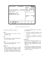
14-1.2
Monitor Mode Testing
To setup for Monitor mode testing, put the analyzer
in SECURENET mode, and in the RF zone select
Monitor mode. Select the desired settings for each
cursor position in the RF zone. Select the
corresponding softkey for the Mon RF In cursor
location. There are two choices: ANT and RF I/O
port. The ANT port accesses the analyzer's
sensitive receiver and should be used for strictly
"off the air" measurements. If ANT is used, attach
the supplied antenna to the ANT port. The RF I/O
port should be used for direct connection to the
radio under test. If RF I/O port is used, connect a
coaxial cable from the analyzer's input port to the
radio's output port.
Select the desired meter and display needed to
perform the test. See the General Operations table
191
Summary of Contents for R2600 Series
Page 8: ...3 7 1 3 AC DC Voltmeter 41 3 7 1 4 INT DIST EXT DIST Meter 43 v...
Page 46: ...This Page Intentionally Left Blank xxxvi...
Page 66: ...DISPLAY ZONE RF ZONE AUDIO ZONE Figure 3 1 Screen Zone Arrangement 20...
Page 68: ...Figure 3 2 System Help 22...
Page 83: ...Figure 3 11 General Sequence Mode Select 37...
Page 85: ...39 Figure 3 12 RF Display Zone...
Page 88: ...Figure 3 14 Digital Voltmeter Screens 42...
Page 102: ...Figure 3 22 Bar Graphs 56...
Page 107: ...Figure 3 24 Memory Screens 61...
Page 128: ...This Page Intentionally Left Blank 82...
Page 202: ...This Page Intentionally Left Blank 156...
Page 205: ...Figure 11 1 R 2670 with SECURENET Option Housing 159...
Page 206: ...This Page Intentionally Left Blank 160...
Page 218: ...Figure 13 8 Test Key Programming Display Figure 13 9 External Key Programming Display 172...
Page 225: ...Figure 13 12 Duplex Mode Display Zone 179...
Page 234: ...VOICE Figure 13 17 CLEAR SCOPE Markers 188...
Page 236: ...This Page Intentionally Left Blank 190...
Page 249: ...Figure 14 8 SECURENET CLEAR SCOPE Display of Output Modulation 203...
Page 252: ...This Page Intentionally Left Blank 206...
Page 256: ...210 This Page Intentionally Left Blank...
Page 267: ...Figure 17 7 Encryption Select Display Figure 17 7 Encryption Select Display 221 221...
Page 286: ...This Page Intentionally Left Blank 240...
Page 291: ...Figure 18 1 Radio BER Test Mode Audio Zone Figure 18 2 Radio BER Test Mode BER Meter 245...
Page 293: ...Figure 18 4 Receive BER 247...
Page 298: ...Figure 18 6 ASTRO CLEAR SCOPE Display of Output Modulation 252...
Page 304: ...Figure 21 1 PROJ 25 Version Screen Figure 21 2 PROJ 25 Options Screen 258...
Page 309: ...Figure 21 6 SET UP Display Screen Figure 21 7 Encryption Select Display 263...
Page 335: ...Figure 22 4 PROJ 25 CONV CLEAR SCOPE Display of Output Modulation 289...
Page 339: ...Figure 24 1 PROJ 25 Version Screen Figure 24 2 PROJ 25 Options Screen 293...
Page 354: ...Figure 25 3 Encryption Select Display Figure 25 4 Algorithm Select Display 308...
Page 369: ...B 6 This Page Intentionally Left Blank...
Page 379: ...This Page Intentionally Left Blank F 4...
Page 383: ...This Page Intentionally Left Blank H 2...
Page 389: ...J 4 This Page Intentionally Left Blank...
Page 393: ...This Page Intentionally Left Blank K 4...