


17-7 ASTRO ENCRYPTION SET UP
17-7.1 SET UP Encryption Display
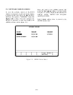
The SET UP display places the analyzer in
encryption setup mode and allows the operator to
select the desired algorithm. The SET UP display
is accessed from the Display Zone. To use SET
UP display, move the cursor to the "Display:"
field and select SET UP using the
SET UP
softkey. The Display Zone will show a menu of
SET UP options as shown in figure 17-6.
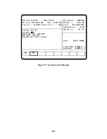
17-7.1.1 Encrypt
The analyzer operates in either clear or encrypted
modes. In the Display Zone, scroll the cursor to
the “Encrypt:” field and select ON as shown in
figure 17-7 for encrypted ASTRO or OFF for
clear ASTRO operation
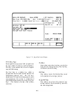
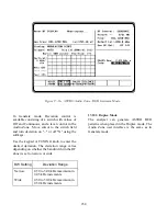
17-7.1.2 Algorithm Select
Within the SET UP display, the first option field
is Algorithm Select. Algorithm is a term that
describes the method of coding data or audio so
that only equipment having the same algorithm
selected, and the same key, are able to exchange
intelligible information. The analyzer includes
several algorithms recognized by radios using
ASTRO. You will need to select one of these
algorithms to use for processing messages.
In the Display Zone, move the cursor to the
"Algorithm Sel:" field as shown in figure 17-8.
The softkeys will provide a menu of the available
algorithms. Select the appropriate algorithm.
Refer to section 17-4 for a description of the U.S.
and International encryption algorithms.
Figure 17-6. SET UP Display Screen
220
Summary of Contents for R2600 Series
Page 8: ...3 7 1 3 AC DC Voltmeter 41 3 7 1 4 INT DIST EXT DIST Meter 43 v...
Page 46: ...This Page Intentionally Left Blank xxxvi...
Page 66: ...DISPLAY ZONE RF ZONE AUDIO ZONE Figure 3 1 Screen Zone Arrangement 20...
Page 68: ...Figure 3 2 System Help 22...
Page 83: ...Figure 3 11 General Sequence Mode Select 37...
Page 85: ...39 Figure 3 12 RF Display Zone...
Page 88: ...Figure 3 14 Digital Voltmeter Screens 42...
Page 102: ...Figure 3 22 Bar Graphs 56...
Page 107: ...Figure 3 24 Memory Screens 61...
Page 128: ...This Page Intentionally Left Blank 82...
Page 202: ...This Page Intentionally Left Blank 156...
Page 205: ...Figure 11 1 R 2670 with SECURENET Option Housing 159...
Page 206: ...This Page Intentionally Left Blank 160...
Page 218: ...Figure 13 8 Test Key Programming Display Figure 13 9 External Key Programming Display 172...
Page 225: ...Figure 13 12 Duplex Mode Display Zone 179...
Page 234: ...VOICE Figure 13 17 CLEAR SCOPE Markers 188...
Page 236: ...This Page Intentionally Left Blank 190...
Page 249: ...Figure 14 8 SECURENET CLEAR SCOPE Display of Output Modulation 203...
Page 252: ...This Page Intentionally Left Blank 206...
Page 256: ...210 This Page Intentionally Left Blank...
Page 267: ...Figure 17 7 Encryption Select Display Figure 17 7 Encryption Select Display 221 221...
Page 286: ...This Page Intentionally Left Blank 240...
Page 291: ...Figure 18 1 Radio BER Test Mode Audio Zone Figure 18 2 Radio BER Test Mode BER Meter 245...
Page 293: ...Figure 18 4 Receive BER 247...
Page 298: ...Figure 18 6 ASTRO CLEAR SCOPE Display of Output Modulation 252...
Page 304: ...Figure 21 1 PROJ 25 Version Screen Figure 21 2 PROJ 25 Options Screen 258...
Page 309: ...Figure 21 6 SET UP Display Screen Figure 21 7 Encryption Select Display 263...
Page 335: ...Figure 22 4 PROJ 25 CONV CLEAR SCOPE Display of Output Modulation 289...
Page 339: ...Figure 24 1 PROJ 25 Version Screen Figure 24 2 PROJ 25 Options Screen 293...
Page 354: ...Figure 25 3 Encryption Select Display Figure 25 4 Algorithm Select Display 308...
Page 369: ...B 6 This Page Intentionally Left Blank...
Page 379: ...This Page Intentionally Left Blank F 4...
Page 383: ...This Page Intentionally Left Blank H 2...
Page 389: ...J 4 This Page Intentionally Left Blank...
Page 393: ...This Page Intentionally Left Blank K 4...