Equipment overview:
Theory of operation
2000966-542D
Dash 3000/4000/5000
2-33
Optional CARESCAPE Network communication
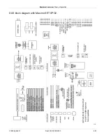
The microprocessor provides an Ethernet controller, which is
implemented on SCC1 in order to benefit from the additional buffer
descriptors compared to SCC2. Ethernet packets are stored in SRAM
buffers and are transmitted and received by the 10BASE-T transceiver.
The Ethernet clocks are generated from a 20 MHz crystal oscillator
circuit and the transceiver. The transceiver also provides a visual
indication in the form of four LEDS to identify packet transmit, receive,
collision, and link integrity. The status of received data is indicated by
the link integrity signal, which is used by the microprocessor to
determine if the patient monitor is connected to the CARESCAPE
Network.
An isolation transformer provides basic insulation to the twisted pair
interface required to meet the ANSI/IEEE 802.3 standard (Ethernet).
Isolation is required because during transport the power cord with the
ground conductor is not available to provide a path for a fault condition.
An 8-pin RJ-45 port containing two isolated, differential pairs is provided
to connect the patient monitor to a network hub.
NOTE
Power is not provided in the twisted pair interface as in the
attachment user interface (AUI) of other monitoring products.
Ethernet priority
Ethernet communications are prioritized in the following order.
1. Top priority is the Peripheral Expansion interface.
2. Next priority is the Hardwired Ethernet connection at the back of the
patient monitor.
3. Lowest priority is the optional wireless connection.
If none of the above exist, then the patient monitor is a stand-alone
monitor.
Async communication
Asynchronous communication ports comply with the GEMMS AutoPort
protocol and are provided through an 8-pin RJ-45 port and the 20-pin
peripheral interface described in the next section.
Summary of Contents for 001C 051D 003A
Page 10: ...viii Dash 3000 4000 5000 2000966 542D ...
Page 11: ...2000966 542D Dash 3000 4000 5000 1 1 1 Introduction ...
Page 20: ...Introduction Service information 1 10 Dash 3000 4000 5000 2000966 542D ...
Page 21: ...2000966 542D Dash 3000 4000 5000 2 1 2 Equipment overview ...
Page 64: ...Equipment overview Theory of operation 2 44 Dash 3000 4000 5000 2000966 542D ...
Page 65: ...2000966 542D Dash 3000 4000 5000 3 1 3 Installation ...
Page 73: ...2000966 542D Dash 3000 4000 5000 4 1 4 Configuration ...
Page 99: ...2000966 542D Dash 3000 4000 5000 5 1 5 Preventive maintenance ...
Page 117: ...2000966 542D Dash 3000 4000 5000 6 1 6 Troubleshooting ...
Page 146: ...Troubleshooting Wireless LAN 6 30 Dash 3000 4000 5000 2000966 542D ...
Page 147: ...2000966 542D Dash 3000 4000 5000 7 1 7 Field replaceable units ...
Page 201: ...2000966 542D Dash 3000 4000 5000 8 1 8 Functional and electrical safety checks ...
Page 257: ...2000966 542D Dash 3000 4000 5000 A 1 A Electromagnetic compatibility EMC ...
Page 267: ...2000966 542D Dash 3000 4000 5000 B 1 B Network troubleshooting ...
Page 279: ...2000966 542D Dash 3000 4000 5000 D 1 D Checklist ...
Page 281: ......


