Ch04 Main Circuit Terminals | VFD-ED
4-2
Main input power terminals
Do not connect a three-phase model to one-phase power. R/L1, S/L2 and
T/L3 have no phase-sequence requirement and can be connected in any
sequence.
You must install a NFB between the three-phase power input terminals and
the main circuit terminals (R/L1, S/L2, T/L3). Add a magnetic contactor (MC)
to the power input wiring to cut off power quickly and reduce malfunctions
when the AC motor drive protection function activates. Both ends of the MC
should have an R-C surge absorber.
Tighten the screws in the main circuit terminal to prevent sparks caused by
screws loosened due to vibration.
Use voltage and current within the specifications in Chapter 08.
When using a general ELB (Earth Leakage Breaker), select a current sensor
with sensitivity of 200 mA or above and not less than 0.1 second operation
time to avoid nuisance tripping. When choosing an ELB designed for the AC
motor drive, choose a current sensor with sensitivity of 30 mA or above.
Use shielded wire or conduit for the power wiring and ground the two ends of
the shielding or conduit.
Do NOT run and stop the AC motor drives by turning the power ON and
OFF. Run and stop the AC motor drives by sending the RUN and STOP
commands through the control terminals or the keypad. If you still need to
run and stop the AC motor drives by turning the power ON and OFF, do so
no more often than ONCE per hour.
Output terminals of the main circuit
When it is necessary to install a filter at the output side of the AC motor drive
terminals U/T1, V/T2, W/T3, use an inductance filter. Do not use
phase-compensation capacitors or L-C (Inductance-Capacitance) or R-C
(Resistance-Capacitance) capacitors.
DO NOT connect phase-compensation capacitors or surge absorbers at the
output terminals of AC motor drives.
Use well-insulated motors to prevent any electric leakage from the motors.
Use terminals [+1, +2] for connecting a DC reactor.
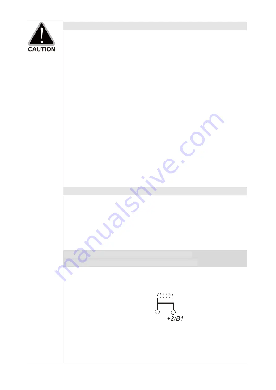
Use terminals [+1, +2/B1] for connecting a DC bus.
Use these terminals to connect a DC reactor to improve the power factor
and reduce harmonics. A jumper is connected to these terminals at the
factory. Remove that jumper before connecting to a DC reactor.
+1
Jumper
DC reactor
Models above 22 kW do not have a built-in brake resistor. To improve
resistance braking, connect an optional external brake resistor.
When not in use, leave ter2/B1, (
-
) open.
Short-circuiting [B2] or [
-
] to [+2/B1] damages the motor drive. Do NOT
short-circuit those terminals.
Summary of Contents for VFD-ED Series
Page 3: ......
Page 10: ...Ch01 Introduction VFD ED 1 3 1 2 Model Name 1 3 Serial Number...
Page 21: ...Ch01 Introduction VFD ED 1 14 Built In Keyboard Panel KPED LE01 Unit mm inch...
Page 26: ...Ch02 Installation VFD ED 2 5 Ambient Temperature Derating Curve Altitude Derating Curve...
Page 27: ...Ch02 Installation VFD ED 2 6 The page intentionally left blank...
Page 28: ...Ch03 Wiring VFD ED 3 1 Chapter 3 Wiring 3 1 Wiring 3 2 System Wiring Diagram...
Page 30: ...Ch03 Wiring VFD ED 3 3 3 1 Wiring...
Page 32: ...Ch03 Wiring VFD ED 3 5...
Page 38: ...Ch04 Main Circuit Terminals VFD ED 4 3 4 1 Main Circuit Diagram Frame B Frames C D Frame E...
Page 46: ...Ch05 Control Terminals VFD ED 5 3 Frame E Step 1 Step 2 Step 3...
Page 47: ...Ch05 Control Terminals VFD ED 5 4 5 2 Control Terminal Specifications...
Page 51: ...Ch05 Control Terminals VFD ED 5 8 The page intentionally left blank...
Page 94: ...06 Optional Accessories VFD ED 6 43 EMC Filter Model B84143D0150R127 Unit mm inch...
Page 95: ...06 Optional Accessories VFD ED 6 44 EMC Filter Model B84143D0200R127 Unit mm inch...
Page 96: ...06 Optional Accessories VFD ED 6 45 EMC Filter Model B84142A0042R122 Unit mm inch...
Page 242: ...Ch12 Descriptions of Parameter Settings VFD ED 12 31 Elevator Timing Diagram...
Page 313: ...Ch12 Descriptions of Parameter Settings VFD ED 12 102 The page intentionally left blank...
Page 317: ...Ch13 Warning Codes VFD ED 13 4 The page intentionally left blank...
Page 329: ...Ch14 Fault Codes VFD ED 14 12 The page intentionally left blank...
Page 351: ...Ch16 Safe Torque Off Function VFD ED 16 10 16 5 6 STL1 Figure 6 16 5 7 STL2 Figure 7...
Page 353: ...Ch16 Safe Torque Off Function VFD ED 16 12 The page intentionally left blank...
Page 373: ...Appendix A EMC Standard Installation Guide VFD ED A 20 The page intentionally left blank...
Page 389: ...Appendix B Revision History VFD ED B 16 The page intentionally left blank...


