Ch12 Descriptions of Parameter Settings
| VFD-ED
12-69
Emergency Stop (EF) & Forced Stop
Control Mode
VF VFPG SVC
FOCPG FOCPM
Default:
0
Settings
0: Coast to stop
1: According to deceleration Time 1
2: According to deceleration Time 2
3: According to deceleration Time 3
4: According to deceleration Time 4
5: According to Pr.01-31
When the multi-function input terminal is set to 10 or 18 and is ON, the drive operates according to this
parameter setting.
Time for Decreasing Torque at Stop
Control Mode
FOCPG
FOCPM
Default:
0.000
Settings 0.000–5.000 sec.
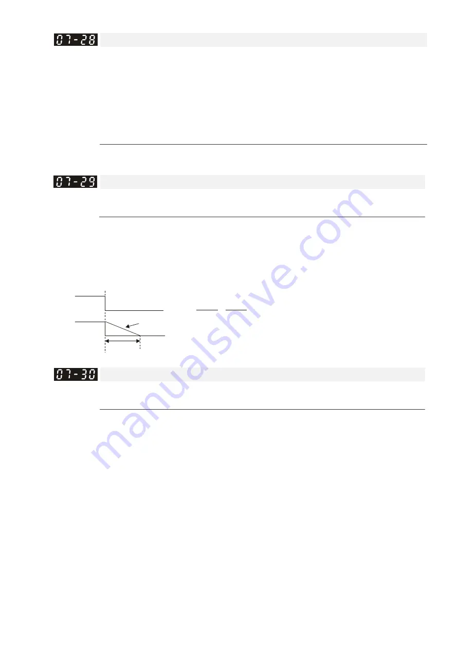
When the elevator is stopped and the mechanical brake is engaged, the drive stops output. At the same
time, it produces noise from the reacting force between the motor and the mechanical brake. Use this
parameter to decrease this reacting force and lower the noise.
Sets the time when torque decreases from 300% to 0%.
RUN/STOP
0%
i
t
i
00-01 x
100%
300% x (07-29)=t
DC Brake Current Level at Stop
Control Mode
VF
VFPG
SVC
Default:
0
Settings
0–100% of the rated current of the motor drive
Sets the level of the DC brake current output to the motor at stop. When setting the DC brake current, the
rated current (Pr.00-01) is 100%. It is recommended that you start with a low DC brake current level and
then increase until you reach the proper holding torque. However, the DC brake current cannot exceed the
motor’s rated current to prevent the motor from burnout. Therefore, DO NOT use the DC brake for
mechanical retention, otherwise injury or accident may occur.
When in FOCPG/FOCPM control mode, you can enable the DC brake without setting up Pr.07-30.
Summary of Contents for VFD-ED Series
Page 3: ......
Page 10: ...Ch01 Introduction VFD ED 1 3 1 2 Model Name 1 3 Serial Number...
Page 21: ...Ch01 Introduction VFD ED 1 14 Built In Keyboard Panel KPED LE01 Unit mm inch...
Page 26: ...Ch02 Installation VFD ED 2 5 Ambient Temperature Derating Curve Altitude Derating Curve...
Page 27: ...Ch02 Installation VFD ED 2 6 The page intentionally left blank...
Page 28: ...Ch03 Wiring VFD ED 3 1 Chapter 3 Wiring 3 1 Wiring 3 2 System Wiring Diagram...
Page 30: ...Ch03 Wiring VFD ED 3 3 3 1 Wiring...
Page 32: ...Ch03 Wiring VFD ED 3 5...
Page 38: ...Ch04 Main Circuit Terminals VFD ED 4 3 4 1 Main Circuit Diagram Frame B Frames C D Frame E...
Page 46: ...Ch05 Control Terminals VFD ED 5 3 Frame E Step 1 Step 2 Step 3...
Page 47: ...Ch05 Control Terminals VFD ED 5 4 5 2 Control Terminal Specifications...
Page 51: ...Ch05 Control Terminals VFD ED 5 8 The page intentionally left blank...
Page 94: ...06 Optional Accessories VFD ED 6 43 EMC Filter Model B84143D0150R127 Unit mm inch...
Page 95: ...06 Optional Accessories VFD ED 6 44 EMC Filter Model B84143D0200R127 Unit mm inch...
Page 96: ...06 Optional Accessories VFD ED 6 45 EMC Filter Model B84142A0042R122 Unit mm inch...
Page 242: ...Ch12 Descriptions of Parameter Settings VFD ED 12 31 Elevator Timing Diagram...
Page 313: ...Ch12 Descriptions of Parameter Settings VFD ED 12 102 The page intentionally left blank...
Page 317: ...Ch13 Warning Codes VFD ED 13 4 The page intentionally left blank...
Page 329: ...Ch14 Fault Codes VFD ED 14 12 The page intentionally left blank...
Page 351: ...Ch16 Safe Torque Off Function VFD ED 16 10 16 5 6 STL1 Figure 6 16 5 7 STL2 Figure 7...
Page 353: ...Ch16 Safe Torque Off Function VFD ED 16 12 The page intentionally left blank...
Page 373: ...Appendix A EMC Standard Installation Guide VFD ED A 20 The page intentionally left blank...
Page 389: ...Appendix B Revision History VFD ED B 16 The page intentionally left blank...


